This thread has been locked.

If you have a related question, please click the "Ask a related question" button in the top right corner. The newly created question will be automatically linked to this question.

OPA381 Stability Question

Other Parts Discussed in Thread: OPA381, OPA380

Team,

Can you please assist me with the following OPA381 stability question that came from JDSU?

Please read customer's comments for details.

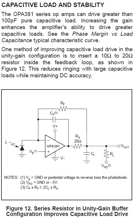
"In the OPA381 data sheets, I read the max cap, which is 100 pF to have decent margin. RS=0, in our case. In the figure (top left), 50K (RF) is

In parallel with 100 pF (CF). If we assume our load is not capacitive, say, it is 1K ohm to the ground.


For some applications, we need BW as low as 10 KHz for our TIA. Can we have CF > 100 pF ;


For an example,   f 3-dB =  1/ (2piRFCF)   -à  50K and 1 nF  =>  f 3-dB = 3.18 KHz.  Would this CF = 1nF create in instability or erode into phase margin?

Note: OPA381’s cost is very attractive for low-cost products, I plan to go for OPA381 in place of OPA380."

  • Kareem,

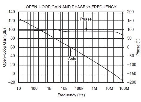
    If your load is purely resistive, the OPEN-LOOP GAIN and PHASE plot (below) shows around 90 degrees phase margin in unity gain - very stable.


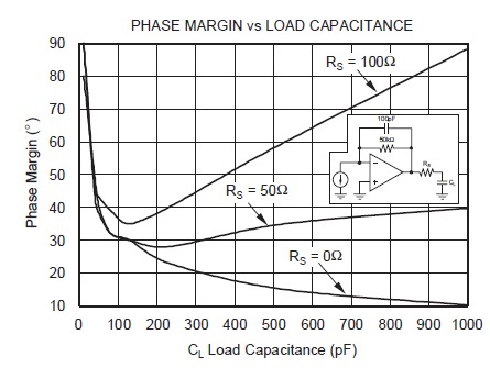
    If your load is capacitive, please see the graph of Phase Margin vs Load Capacitance at the bottom of this post.  Any phase margin less than 30 degrees should be considered unstable, thus looking at the graph below, the OPA381 can drive in a unity gain only 100pF unless you add Rs at the output. 

    If you place the OPA381 in a gain of 1000, its close-loop gain will be lowered to 18kHz (18MHz/1000) and its stability will greatly improve - in gain of 1000, OPA381 should comfortably be able to drive 1nF without any Rs.  In  the case of the buffer configuration, however, you will need to add Rs of at least 20-30 ohms in order to increase the phase margin to above 30 degrees (refer to the figure at the bottom) - it shows 40 degrees phase margin with Rs=50ohm and CL=1nF.


    Marek