This thread has been locked.

If you have a related question, please click the "Ask a related question" button in the top right corner. The newly created question will be automatically linked to this question.

XTR110 enable/disable circuit

Other Parts Discussed in Thread: XTR110, XTR111

Hello. My circuit uses a XTR110 to translate a voltage signal from 0-10V to 4-20mA, using the basic circuits from its datasheets, with a P-MOS at the output to drive the load.

I need that the output current be 0mA when a fail is detected in other sections of the system. The fail signal is CMOS/TTL.

In the image below I propose an implementation based on the Ouput Enable circuit from the XTR111 datasheet. The switch would be implemented with a small signal MOS transistor, with its gate controlled by the fail signal previuosly mentioned. My concern is about the 3k resistor in the gate of the Qext transistor, how it will affect the control loop from the XTR110.

Reeplacing the XTR110 for a XTR111 is not an option (for now). The input signal range can be modified if needed.

Is there another more elegant solution to implement a ouput enable/disable for the XTR110 to indicate a fail in the system?

Best regards,

Mr. Electron.

  • Hello,

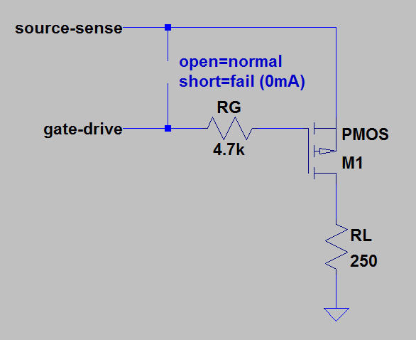
    The output disable circuit in the XTR111 works by shorting the PMOS gate signal to PMOS source voltage.  The short results in a near zero volt Vgs voltage which turns the PMOS transistor off, preventing current flow.

    While we haven't tested the circuitry you've suggested, it should perform the same task as what's done in the XTR111 and should therefore produce similar results.  The XTR110 gate-drive signal is internally protected against continous shorts to VCC and common (GND) so there won't be any issues with a hard short on the Gate-Drive output through your MOS switch.

  • Hello, I tested the above circuit using a 4.7k ohm resistor in series with the P-MOS gate, and shorting the Gate-Drive output with the transistor source. It works fine, the current drops to 0 mA since the Vgs voltage is 0V.

    Shorting the Gate-Drive ouput with the Source Sense pin, will not damage the IC? The XTR110 doesn't mention that this ouput is internally protected against continuos shorts to VCC/Common.

  • Just so we know exactly what you've built, could you include a simple schematic drawing of the XTR110 output stage with the output disable circuit you've created?
  • The circuit is simply this:

  • Hello,
    We prefer to not recommend something that isn't defined in the product datasheet, so we're a little uneasy about recommeding shorting Gate-drive to Source-sense. Could you rework your circuit such that the switch shorts the gate-drive signal to the +VCC rail, which is a specified condition in the product datasheet?
  • Hello, I'm gonna rework the circuit to do that, you're right. I think shorting gate-drive to Vcc is the most simple workaround to implement an output disable control.

    Thanks! ;)