This thread has been locked.

If you have a related question, please click the "Ask a related question" button in the top right corner. The newly created question will be automatically linked to this question.

LMH3401 Differential output not working

Other Parts Discussed in Thread: LMH3401, TINA-TI

Hello Ti community , 

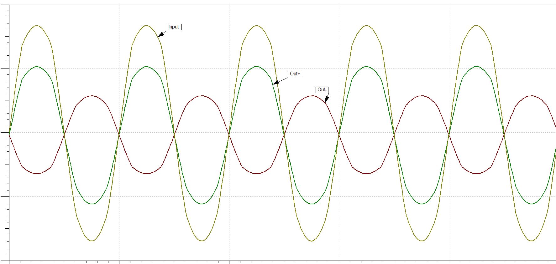
I am using lmh3401 for single to differential conversion , however the simulation and the physical test do not match.( not working as expected) 

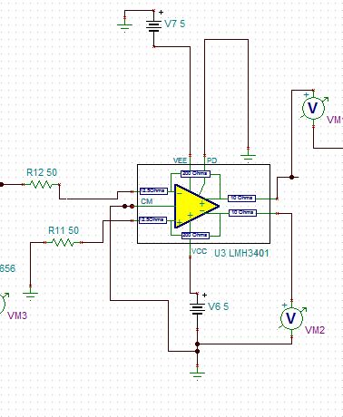
Here is the schematics , the simulation in TIna ti and the physical test results. 
Also inverted output seems to be a little smaller in amplitude than noninverted output in Tina ti. 
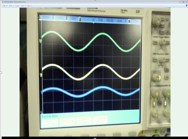
 This is what i am getting out .. Above Green is  input , yellow = out+ , and blue = out- . i expected that out- will be inverted but it is not. ? 

Please any help will be Very much appreciated.. this is for a school project. 

  • Hi Abel,

    Sounds like you are running the LMH3401 off +/-5V (10V total) supplies, according to your TINA-TI schematic. The absolute maximum supply is rated at 5.5V on page 4! So, I think you may have damaged the part.

    You can try running the conditions in the TINA-TI reference design (5V total supply and CM pin at 2.5V) to see if the part is still alive? http://www.ti.com/lit/tsc/sbom909

    Regards,

    Hooman

  • Hi Hooman , 

    That's correct , at first i run it with+/- 5v before discovering that it was hitting up quickly. Therefore i quickly switched to +/-2.5 which works ok then.(so i know i didn't kill it luckily).  Also measuring the output deferentially results in the expected output. Thanks for the suggested design BTW.  Also in the datasheet it is suggested to use a split supply of +/- 2.5 for each VCC and VEE. Wouldnt that make it 10V total?

    Thanks , 

    Abel.  

  • Hi Abel,
    The datasheet states "In this case, VS+ is connected to 2.5 V, and VS– is connected to –2.5 V, while the GND pins are connected to the system ground". In this case, the total supply voltage that the LMH3401 "sees" is 5V (difference between VS+ and VS- potential, not 10V). I actually don't know how you compute 10V total!

    Please explain if I'm missing something in my explanation.


    Regards,
    Hooman
  • Hi Hooman ,
    Am sure this is a stupid question but , since there are 2 Vs+ and 2 Vs- connections , with Vs+ = 2.5V each and Vs- = -2.5V each. would that make it a total of 10V that the component experiences? sorry am still trying to grasp the basics of differential opamps.

    thanks
  • Hi Abel,
    No, the 2 pins for VS- and VS+ do not cause the total supply to be 10V. The total is still 5V with +/-2.5V split supplies.

    Regards,
    Hooman
  • Hello Abel,

    "Therefore i quickly switched to +/-2.5 which works ok then.(so i know i didn't kill it luckily).  Also measuring the output deferentially results in the expected output."


    Even if the part appears to work correctly the noise and distortion performance will be poor and the part will most likely cease to work eventually due to latent damage.   Please consider getting a new part before making critical measurements.


    I have not had any parts survive even 7V and still meet datasheet specifications. 

    Regards,

    Loren


  • Hi Loren , 

    Thanks for the tip.  

    This is actually a test circuit , so  i have another new  part that i will mount on my PCB.  

    Regards , 

    Abel.