This thread has been locked.

If you have a related question, please click the "Ask a related question" button in the top right corner. The newly created question will be automatically linked to this question.

INA149

Other Parts Discussed in Thread: INA149, TINA-TI

Hi!

I use INA149 and/or AD629 in my design - see schematics.

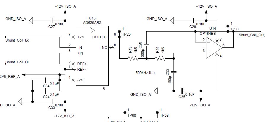
I've experienced gain>1 (actually it was about 2) for input signal ~ 330kHz (+-200mV). I've done test without loading the output with the same gain @ 330kHz.

It could be caused by a high capacitive load, but there is only very short track with R13 unsoldered, so there's no reason for a high parasitic capacity.

OpAmp input is directly connected to a signal generrator with 50Ohm impedance.

Have anybody experienced similar behaviour of INA149 or AD629?

Thanks

  • Hello,

    This is likely an issue with how you're terminating your signal source.  Please refer to the following article and let us know if you have any questions.

    www.eetimes.com/author.asp;doc_id=1225569

  • Here is the link again:

    www.eetimes.com/author.asp;doc_id=1225569
  • For some reason, I'm having an issue pasting the link.  Therefore try clicking here.

  • Hi Pete,

    thanks for your reply.
    Examples in the linked article describe and explain 'termination issues' leading to the gain lower than expected. In my case, I see the output signal with a doubled amplitude.

    Let me discrribe it agaim:
    I've got signal generator with 50 Ohm impedance at U13 input (see schemaatics in my 1st post).
    Scope probes across input as well (in parallel).
    For unloaded U13 (R13 unsoldered) and for 330 kHz input freq (+-100mV) I can see +-200mV at U13 output (scope probes again).

    I don't think there is so high parasitic capacitance of my PCB loading the output and causing the gain error. Actually the gain is aproximately 1 forr frreq < 300 Hz, it reaches max at 330 kHz and then drops down as the freq rises.

    Any recommendation for experiemnts and testing and for circuit modification?

    For a final application we will have 0.1 Ohm shunt resistor at the INA149 input. Signal generaator is used just for testing.

    Note: AD629 in my schematics is just a placeholder as this model was in our library and the footprint and pins are the same.

    Thanks

    Petr
  • Hello,

    Sorry for the delay.

    I do not suspect capacitive loading causing this issue, especially since you completely disconnect the output by removing R13.

    Let's start here:

    1) Disconnect "Shunt_Coil_Lo" and "Shunt_Coil_Hi" and R13.
    2) Connect pin 2 (-IN) to ground.
    3) Change the impedance of your signal source from 50ohms to High-Z.
    4) Set signal source to provide a 1Vp (2Vpp) sine wave at 330kHz and connect it to pin 3 (+IN).
    5) The output should be as shown below. Please note that it is centered about 2.5V because of the reference given in your schematic (2V5_REF_A).

    I have attached the TINA-TI simulation file. Please let me know if your bench test matches the simulation above.petr.TSC

  • Hi Pete,

    thanks forr support. Actually, I've definitely replaced AD629 by INA149 as with INA149 there's no frequency anomaly.
    However, now I have PSRR concerns.
    I'll initiate extra thread.

    Thaanks for now.

    Petr