This thread has been locked.

If you have a related question, please click the "Ask a related question" button in the top right corner. The newly created question will be automatically linked to this question.

LM770x capacitive loading

Other Parts Discussed in Thread: LMP7701, OPA336

I'm using a LMP7701, powered from 5V, as a voltage buffer on an ADC's internal bias voltage (~2.5V). It will drive several opamp inputs, totalling about 100pF. The datasheet suggests adding some isolation resistance for "heavy" capacitive loads, but I don't see any graphs or calculations to assist with this or to define what "heavy" means. How can I know the stable range for load/output capacitance of LMP7701 versus various series or parallel load resistances?

The OPA336 datasheet, for example, gives a nice graph in Figure 5 to show the stable region for a variety of configurations.

  • Hi Evan,

    "Heavy" generally means greater than 100pF. Most low power op-amps do not like capacitive loads greater than 100pF.

    There is a gain-phase plot vs Cload on page 13 (Fig 31).

    For 100pF, there is a minimum of 60° of phase margin - so you should not have a problem driving 100pF.

    Though it is still recommended to place a resistor in series with the output - especially driving a ADC. The resistor is usually chosen by trial and error in the actual circuit since no generic bench setup will exactly duplicate the actual circuit dynamic conditions. Start with a R value around 50 ohms and increase until proper settling occurs.

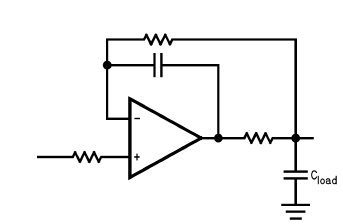
    If you are worried about voltage sag, you can take the feedback from the load side of the isolation resistor (as seen below), but a small (starting at 10pF) cap will be need to be added between the output and inverting input to maintain stability.

    The feedback resistor is optional - but recommend. Does not need to be large, 1K or so. The resistor on the input is optional, too (just happens to be in the graphic).

    Regards,

  • Thank you, Paul.

    To be clear, I'm not driving an ADC. This is buffering the ADC's bias voltage, and then passing that buffered voltage to op amps. The ADC is the input to my LMP7701.

    For my circuit, the input is a DC voltage and the output is going into high impedance (opamp inputs). So there's no appreciable voltage drop to worry about and I don't need to consider any usable bandwidth range. In that case, it seems the simpler circuit from the datasheet with one resistor outside the feedback loop will work just as well. Is that right?

    And what about driving a much larger capacitance, like 1uF or 10uF or 100uF? What are the recommendations in that case?
  • Hi Evan,

    Same recommendations. Even the "reference" input of an A/D can have dynamic transients at sample time.

    The two-stage feedback shown above is suitable for large caps (>1uF), too (and only at DC or very low frequencies).

    Those output caps are AC shorts, and trying to move the output quickly (AC signal) causes large output currents as the amp tries to charge/discharge the capacitor. The output won't move very fast with that much weight on it.

    But at DC, the amp is basically keeping the cap topped-off - so no real current is flowing during steady-state times.

    Keep in mind that very large capacitors (>1uF) will take some time to charge when power is first applied - as you only have a few tens of mA of charge current due to current limiting of the amp output.

    One thing to be careful of when placing large (>10uF) capacitors on the output is that when the power supply is removed - the cap can briefly back-feed through the output and back to the supply through the forward-biased ESD diode (between the output and the supply pin). This can degrade the ESD diode over time if the current is high. The series resistor should limit this current - and it should be limited to the abs max current rating. So 2.5-0.8V/10mA =170 ohm minimum.

    Regards,
  • Thank you again, Paul.