This thread has been locked.

If you have a related question, please click the "Ask a related question" button in the top right corner. The newly created question will be automatically linked to this question.

OPA549 single supplied?

Other Parts Discussed in Thread: OPA549

Hi,

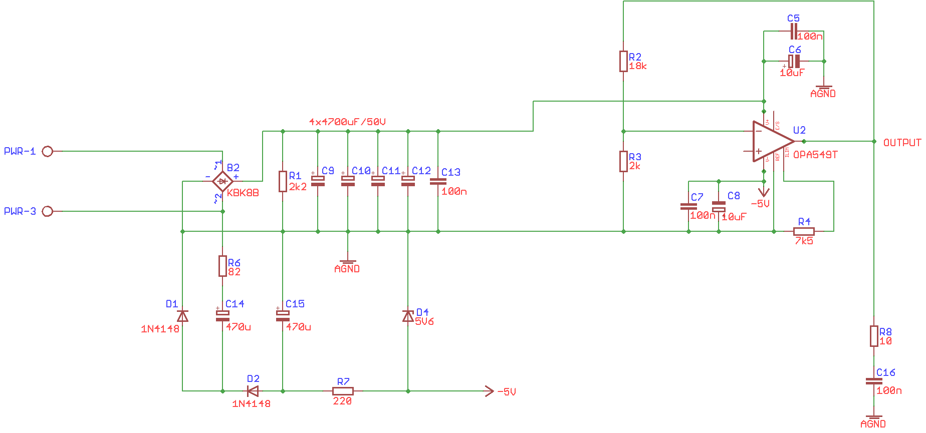
I'd like to design simple power supply with OPA549as a power source  but the goal is to use single power supply (30V, 5A) for the opamp. What is the minimum output voltage with the OPA549 supplied this way? The datasheet gives the range from 1V...but would be possible to have the range started from 0V? I would use simple charge pump to obtain negative rail (for example -5V) in order to have the range from 0V  but this way the negative rail would have small maximum output current. Why I want to use this solution? Because I have the power transformer with one output voltage. Could you give me some tips? Best regards... Robert

  • Robert,

    Almost all op amps can be used in single or dual configuration and OPA549 is no exception.  However, since most of the specifications like input common-mode voltage or output voltage range are specified with respect to the supply rails (see table below), you have to make sure you do not violate such conditions. 

    Looking at the Output Voltage Swing vs Output Current graph below, you may expect around 3.5V swing to positive rail while sourcing 5A and 2.5V swing to negative rail while sinking 5A.


    Therefore, using +30V and -5V supplies you mentioned, OPA549 minimum output voltage swing under Iout=5A load would be from:  (-5V+2.5V)=-2.5V to maximum of: (30V-3.5V)=26.5V 

  • Hi Mark!
    Thank you. I knew that it is possible but the question is slightly different (sorry if I described this wrong way). Can I use negative rail with small current capability like simple negative charge pump (powered from positive rail power source)? The device (programmable power supply) uses simple power transformer 30V/5A and there is no chance to built fully capable negative rail power source. So the question is: can I use 30V/5A as a positive rail power source and, for example, -5V/100mA as a negative rail power source with respect to desired output voltage and current capability 0...25V @5A? If not, is there simple solution to do this? The minimum output voltage range could be 1...25V @ 5A. Thank you in advance...Robert
  • Robert,

    In order to have 5A sinking/sourcing capability positive AND negative supply must be able to handle 5A current load. However, if you only need to source 5A output current, your negative supply must be able to handle only OPA549 maximum quiescent current of 35mA.
  • Hi Mark,

    Thank you for your answer. So, to summarise: in the application like programmable power supply (datasheet page 13, figure 10) where the OPA549 is used as a power source (only source, not sink) and output power requirements are: voltage range 0...25V, maximum output current 5A, I CAN use following power sources for supplying the OPA549:

    V+ -> 30V/5A
    V- -> -5V/50mA

    Right? And you are absolutely sure that the OPA549 will not "take" from the negative power source more than 35mA in any conditions (taking into accounts that input voltage is always >=0)? So, if it is right I would use simple single power supply (for positive rail) and charge pump for negative rail as shown below (attached file). Right?

    So, there is still one problem unsolved. Look at the figure 10 (datasheet, page 13). The application uses single power supply with V+=30V and V-=0V...and the Texas wrote: Vo = 1V to 25V and Io = 0 to 10A! Output voltage started from 1V??? Why not from 3.5 or even from 4.5V (output swing shown on charts). Anyway, could you look at the schematic above? Best regards... Robert

  • Robert,

    The ultimate test is to breadboard the circuit and confirm that it works as envisioned before going into production. A negative power supply should only need to sink DC quiescent current of OPA549 and, in case of sudden lowering of the OUTPUT voltage, also AC transient current coming from the load. For that reason, there will be some delay in the OUTPUT settling time when the negative supply’s max 50mA sinking capability is exceeded by the transient loading demand of dt=~C*dV/Iout.

    There is no inconsistencies in the Fig 10 of the datasheet; if you look at the Output Voltage Swing vs Output Current graph above, you will see that under unloaded (sinking) conditions the output can swing within less than 1V above negative rail while under maximum 10A (sourcing) load it can get only within 5V below positive rail. Therefore, on 0 to 30V supplies, the OUTPUT can swing from 1V (Vo=0V+1V, Iout=0) to 25V (Vo=30V-5V, Iout=10A). The 3.5V swing from negative rail applies only under 5A sinking current.

  • Hi Mark,
    So, now I'm not sure if charge pump working as negative rail power source shown above is good choice in this application since OPA549 can sink more than 50mA from this source :-(. I'm not able to estimate if 100mA or more is sufficient in any conditions to have stable output power supply. What do you think about it? Robert

  • Robert,

    I am not sure where the confusion comes from. Your DC power supply circuit as shown above should work with 50mA sinking supply. The only thing to be aware of is that as you suddenly lower the supply voltage (I am not sure if you would ever have to change the output voltage on the fly), there will be some time delay before the Output settles to a new value – once it settles, the circuit should perform as expected.
  • Mark,

    As the circuit will act as arbitrary power supply (that is programmable) the output voltage can be set via remote controller every 1ms (for every 1ms the difference between previous and the next output voltage can be 25V!). So, I'm not sure if the negative rail power source shown above is sufficient in this case. The alternative is to use additional small power transformer wind (for example 300-400mA) and 7905 to supply negative rail...Robert

  • Robert,

    I did not realize that you plan to reprogram the power supply every 1ms. However, with 100nF load you show on your schematic, this still would be feasible since it would take at most 0.167ms of slewing time to bring the Output to a new output setting: dt = C*dV/Iout = 100E-9*25/(50mA-35mA) = 0.000167 seconds.

    Marek

  • Hi Mark,
    Thank you for your answer and enormous help! The simple RC circuit you have mentioned is not the load but simple circuit for stabilizing output (for difficult loads - datasheet). As the device is power supply the load depends on what you connect to the output and the result can be unpredictable this way. So, the settling time can be longer if the negative rail power supply would have insufficient current capability. Right? In this case I would have to use better negative power supply, for example typical circuit with 7905... Robert
  • Robert,

    Yes, that is correct - you have to know TOTAL active load in order to calculate the OUTPUT settling time with the very limited negative supply sinking current capability. Using LM7905 with its peak current of 2.2A should greatly mitigate the problem BUT since it is nothing other than a negative voltage LDO, it requires a negative supply of  -7V to -20V to provide the fixed -5V rail – see PDS table below. Thus your power transformer would also have to include a rectifier to supply the required negative voltage of at least -7V.

    Marek

  • Marek,

    OK. I know that I should use typical application provided for the 7905 to provide the fixed -5V rail but since the settling time depends on the actual OPA's negative rail current (that is when the negative supply’s max sinking capability is exceeded by the transient loading demand) the question is how to estimate this current in any conditions? In other words, how to estimate the maximum negative rail capability for the worst case (worst load type)? Best regards...Robert

  • Robert,

    Please call me: +1 520-750-2162