Hi.
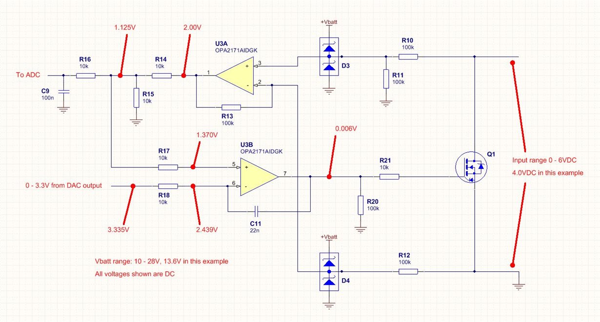
Please refer to the attached screenshot of the simplified circuit. This is used in a DC application.
Notes:
1. The negative input is not necessarily at circuit ground potential and the output FET driver has been simplified to just Q1.
2. Not shown is that Q1 can be disabled and has been for these voltage measurements.
3. I cannot see any signs of instability on my 'scope, and the presence of C11 doesn't affect any results.
4. I originally used an LM258 which worked fine except it suffered from input phase reversal so I opted for the OPA2171 which appears to have other issues in my circuit. I'm wondering if the input phase reversal protection in the OPA2171 has anything to do with this.
I'm using both devices in the OPA2171. The first one (U3A) is a simple differential amp. This part of the circuit is working without issue.
The second amp (U3B) is causing me to scratch my head a bit. If you examine the various voltages you can see there is current flowing through R18 and R17 which is affecting operation. It appears there is a current path between the inverting and non-inverting inputs. Am I over-loading these inputs in any way? The LM258 doesn't present this problem.
Any help would be appreciated.
Regards,
Brendon.


