This thread has been locked.

If you have a related question, please click the "Ask a related question" button in the top right corner. The newly created question will be automatically linked to this question.

INA126 application configuration

Other Parts Discussed in Thread: INA126, TPS65130, PGA280, INA826, TINA-TI

I have a 5kg load cell that was chosen because of some existing conditions.  Its output goes into a load cell amplifier who's output can be either 0-5 volts or 0-10 volts.  The weight of its own physical holding structure accounts for 20% of its initial starting value i.e. 0-5 starts nearly at 1 volt and 0-10 is nearly 2 volts.  I am only interested in the weight of up to 50 grams on the scale so theirs not much change in the output when the weight is added though I can magnify this through the use of the op amp.  I would like the end result of my weighing of 0-50 grams to be a value close to 0-5 volts so that I can read it into an A to D converter on my micro.

Initially I just thought I could use a non inverting op amp for it but later realized it would only magnify my result and not provide me the difference needed for scaling.  I then assumed I would need an instrumentation amplifier style circuit to provide me with a usable amplified value and picked the INA126.  This should give me a usable value that I could amplify to my desired range by providing it a higher supply like say 12 volts and then use its starting range of 2 volts as my zero and amplify it up to 7 volts at my 50 grams full scale.  The difference here being the desired 5 volts.  The question here is if I can reach my 0-5 volt output (or close to) using just a positive power supply or in order to do so I have to use a dual +/- power supply and what then I should attempt to supply pins 2,4 and 5.  Thank you.

  • Would I merely feed the desired offset voltage into Vin- on pin 2 and then ground V- pin 4 and ground pin 5 so it may seem?
  • Hello Mark,

    Is the output of the 'load cell amplifier' different than the output of the INA126? Or, do you plan on using the INA126 as your load cell amplifier?

    I believe that the 'load cell amplifier' has already been selected/integrated. If so, I think your goals are as follows:

    1) Attenuate a single-ended 0-10V signal to 0-5V for your ADC (or simply buffer the output of the 'load cell amplifier' in the 0-5V case).
    2) Subtract your initial offset voltage to increase your dynamic range
    3) Avoid a negative supply voltage if possible

    Is my understanding correct?

  • Pete,
    Yes, the output is different. The 5kg load cell if connected to the load cell amplifier and its dip switch output is set to 0-5 volts it then in turn outputs about 1 volt at the would be zero due to the weight of the scales base plate of 900 grams sitting upon it. If I flip the dip switch to indicate a 0-10 volt swing the load cells corresponding output is like 2 volts of which either way I would like to bring it downward toward zero. The inherent problem is that what I am weighing upon the scale plate is only "up to" an additional 50 grams which in turn hardly provides much of a further output swing from that of the plate itself. This is what I wish to amplify by way of the INA126 and bring its end result closer to a 0-5 volt swing which I can serve as input to my A to D converter.

    A good visual numeric example of the problem is this: Load cell amp output with only plate on it 1.8121 volts, load cell amp output with an additional 50grams on it 1.851 volts. It is this difference which I would like to have a 0-5 volt or (close to) swing. I can add a resistor value to increase the gain across the chip to widen the spread but its shifting the Zero point downward to ground that is the problem given I am starting with a positive value due to the 900gram scale plate and only interested in the additional 50 grams. Realize this is on a would be normal 0-5volt swing across 5kg !

    Thank you
  • Hello Mark,

    Thanks for the additional information.

    So the concept is to place a voltage on VIN- to subtract the 'dc offset voltage' of your sensor (~1V-~2V depending on sensor mode). This is desirable because you could use a positive voltage, whereas a negative voltage is required if you use the Vref pin. In order to measure the sensor offset voltage, however, you would need to ground VIN- and measure the output. For example, if you have 1.8121V on VIN+, and you connect VIN- to ground, the output will be Vout=(1.8121-0)*Gain+Vref where Vref=0. However, the minimum gain of the INA126 (and similar devices) is 5V/V. Therefore the output would become 9.0605V. This would not be good for your 5V ADC. You could try to put a known voltage on VIN+, but it will have to be within 1V of the sensor offset voltage to avoid exceeding the 5V supply. Finally, you will be required to change the gain depending on the sensor mode (0-5V vs. 0-10V) and offset correction (e.g. when measuring the offset you will probably want a gain of 1V/V, but after feeding this voltage back to the input you will want to increase the gain to increase your dynamic range).

    Ultimately my recommendation is to evaluate the PGA280/1. It has separate supply voltages for the input (VSN & VSP) and the output stage (VSON & VSOP). So, you could have +/-15V for the input and a single 5V supply for the output, which interfaces with your microcontroller. You can also easily adjust the gain of the device. Finally, you could use a DAC (discrete or, if applicable, integrated in your microcontroller) to supply the measured sensor offset voltage to the PGA280/1. You will need a dual supply, however that can be accomplished with a 5V supply and the TPS65130.

  • Pete,

    Or I could stick to the path and chip I am using if I were to potentially increase the rail to 12 volts and limit my current so I don't blow the A to D if someone puts too much weight on the scale.  Potentially supply a slight negative voltage to the V- pin allowing it to pull to ground or using something like the TPS65130 offered?

    Can I amplify the slight difference between the scale plate with and without 50 grams on it and spread it out near 0-5 volts using the existing chip so I can read it into an A to D on my micro and if so does it need a negative voltage applied to V- or Vref in order to do so?

    Thank you,

    Mark

  • Pete,

    Here's some values I plugged in for a differential amplifier given if my scale were showing 0.995 volts at rest and fully loaded at 50 grams being 1.005 volts.  If these numbers are right then wouldn't the difference when the weight swings between 0 and 50 therefore then provide a 0-5 volt output?

    Please share your thoughts here too, trying to find an end game in this.  Thanks.

    Mark

  • Hello Mark,

    From what I understand, you want to measure and subtract the offset of your sensor (e.g. 1.8121V) using the INA126.

    The INA126 has an internal gain of 5V/V. Given a sensor offset of 1.8121V, the output of the INA126 will be 9.0605V (assuming VIN+ is grounded). What is the plan for measuring this voltage so that the VIN- potential can be properly adjusted?  As I mentioned before you could try to switch in a known precision voltage instead of connecting VIN+ to ground, but it would have to be within 1V of the unknown sensor offset voltage.  Perhaps you could use a DAC.  If this is feasible, you could use the ADC to measure this voltage and properly adjust the potential at VIN-.  

    On a side note, if you do decide to use the INA126, I recommend using +/-15V supplies because it will maximize your input common-mode range vs. output voltage (please refer to the two graphs at the bottom of page 4 of the data sheet).

    Concerning the difference amplifier...there are a number of things to consider. First, the tolerance of the resistors will contribute offset and gain errors to your system. Secondly, I assume that you will need to change the gain for various reasons. If so, this will likely be done with switches. If so, the Ron (on-resistance) of the switches will further introduce errors in the system. Finally, even small source impedance imbalance will also introduce error. It's for these reasons that devices with high input impedance, integrated laser-trimmed resistors, and adjustable gains are desirable for this type of application. This includes PGAs (e.g. PGA280/1) and instrumentation amplifiers (e.g. INA126).

    Another option is to consider a traditional 3-op amp INA (e.g. INA826). I still recommend +/-15V supplies, but the benefit over the INA126 is that the minimum gain is 1V/V.  

    In the end, however, my recommendation is to use the PGA280/1 solution...no switches or protection circuitry required (though no matter what you will probably need a DAC to drive VIN-).

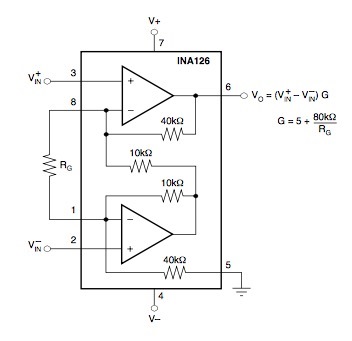
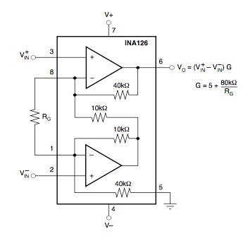
  • Could you please explain the relationship to V-in, V-, and pin 5 as Ground in this image on the spec sheet.  Isn't Vin+ and Vin- the input to a differential amplifier output then given on Vo as shown?  How is this effected by the voltage on V+ and V- ? You mentioned using a +/-15Volt rail swing though if I tie Vin- to ground and then vary the v- voltage via a negative voltage divider leaving the V+ alone or tie pin 4 to ground and vary pin 5 through the voltage divider to pull it down.  Currently I grounded v- and pin 5 and used the voltage divider to pull vin- down.  Which is the intended way to do vary the reference point on this chip ?

    If I intentionally make the Vin- set to a higher value to keep it positive like 4 volts rather than the initial 0.995 to 1.055  then I stay out of the lower end common mode area correct.  I just want the end result magnified and set as close to 0-5 as possible.  It seems as though this is well within the range of what this chip should handle, isn't it ?

  • This is a test post.
  • Hello Mark,

    Sorry for the delay...I'm having issues posting to the forums.  Nonetheless, hopefully this will work.  I have attached my reply as a PDF file.  I have also attached a TINA-TI file.  I hope this works.Mark.pdf

    mark.TSC