This thread has been locked.

If you have a related question, please click the "Ask a related question" button in the top right corner. The newly created question will be automatically linked to this question.

PGA 309 TIPD126 reference board kit programming

Other Parts Discussed in Thread: TIPD126, PGA309EVM-USB, PGA309

I have the PGA309EVM-USB and also got the TIPD126 reference design and assembled it. 

I presume that I can program the TIPD126 reference design by using my PGA309EVM-USB set to do so, however, I was wondering if there exists a more comprehensive setup/hookup other that the illustration I find in the doc  ....sbou024b.pdf. 

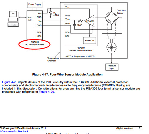
On page 91 it is calling the programming source as the "PC Interface Board".

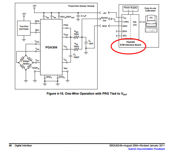
On page 88 it is calling the programming source as the "EVM Interface Board".

I will be using the internal temperature reference and the final product we will be using will be very very close to theTIPD126 and loop powered.

So my questions as follows:

1. Other than the physical hookup as shown, are the "PC Interface Board" and the  "EVM Interface Board" really the same hardware?

2. I won't give the final product access to the the programming pin and only intend to have the product factory programmed, as such there will be no programming pin run to the outside world and will only be accessed during production, so I presume I want to program as shown on page 91?

3. Eventually we would be doing a gang program setup like the Multi-Cal system, but for now just need to program the TIPD126 reference design PCBAs.

4. Is there existing a hookup/cable drawing with the pin out numbers on the cable etc and all other appropriate connections so that one can easily program the TIPD126? It would save me a ton of time.

5. Any pre-made cable to purchase from TI to accomplish item #4?

thanks

  • Hello Michael,

    1. The "PC Interface Board" and the "EVM Interface Board" refer to the same, now obsolete, hardware. The first version of the PGA309EVM used an RS-232 interface but had some issues and was replaced by the current version, PGA309EVM-USB. The PGA309 user's guide was not updated to reflect this in some cases, but the connections shown in these figures are still valid.
    2. Given your application, you can program using a standard four-wire scheme as shown in Figure 91. Since the PRG pin does not need to be accessible in the end product, you should utilize the PGA309's one-wire-disable (OWD) functionality to prevent system noise from causing unwanted EEPROM communication. Simply set the OWD bit to 1 once final calibration is complete, and the module becomes protected from noise at the PRG pin.
    3. We recommend modifying the existing Multi-Cal hardware and software to meet your needs, rather than starting from scratch. This system is quite complex from both a hardware and software perspective and required a significant amount of development time to complete.
    4. The easiest way to see the required connections to the TIPD126 PCB is to consider Figure A-1 in the TIPD126 design document. Simply make your required connections at J1, J2, and J3. Since you plan to use internal temp sense, no connection is required at Vtemp (J2 pin 1).
    5. We do not provide a custom cable to accomplish this. However, you can order cables from Samtec with 100 mil spacing and the desired number of conductors.

    Best regards,

    Ian Williams
    Linear Applications Engineer
    Precision Analog - Op Amps