This thread has been locked.

If you have a related question, please click the "Ask a related question" button in the top right corner. The newly created question will be automatically linked to this question.

High Side current monitoring.

Other Parts Discussed in Thread: INA209, INA215, INA226, INA219, REF2041, INA146, INA149

Hi,

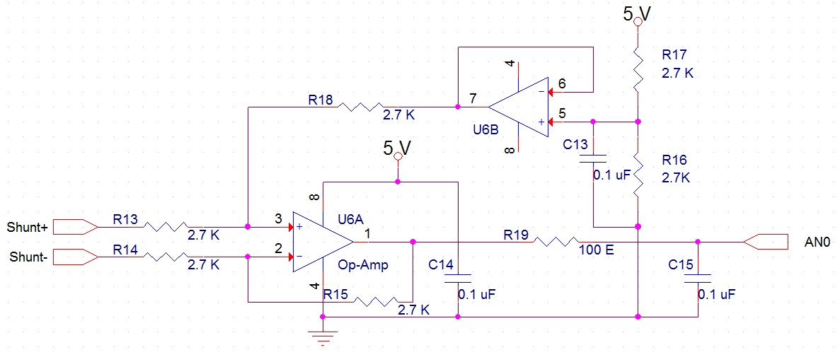
I am trying to monitor High Side current using Rail to Rail Op-Amp. The ouput of that Opamp if interfaced with a microcontroller and applied RMS algorithm and I could monitor with +/- 5 mVolts error, Is their any other method for better results. 

Thanking You,

Ravi.

  • Hello Ravi,

    We have many current shunt monitor solutions for this application, but to help you we'll need more information.

    • What is the common mode voltage range for your application?
    • What is the size of your shunt resistor?
    • What is the current range you are hoping to sense?
    • Are you looking for an analog output device?

    The Current Shunt Monitor FAQ is a great resource to reference.

    Best regards,

    Kareem Moulana

  • Hi Kareem,

    I am not sure about Common mode Voltage,  but the differential voltage across shunt is  75 mVolts  at 500 amps, and the maximum would be 1 Volt.

    The size of the shunt resistor is milli Ohms, Current across Shunt resistor would range from 0 to 10000 Amps for a period of 0.5 Seconds. Current during that period need to be captured. 

    Analog Output or Analog to Digital converter with SPI or IIC would also be fine.

    Thanking You,

    Ravi.

  • Ravi,

    Knowing the common mode voltage is important so that we can recommend the correct part. Is this a high side or low side sensing application?  Low side sensing applications remove most concern about need for large common mode voltages.


    If you intend to sense 75mV @500A then you are looking at a shunt in the microOhms, which is quite low.  Perhaps you could tell us more about your application? That will help us figure out what would work best for you.


    Best regards,

    Kareem Moulana

  • Hi Kareem,

    Shunt is on higher side, Common mode voltage might be less than 15 Volts Ac and hopefully close to "Zero" . The resistance of the shunt should be in micro or milli Ohms. 

    Could you please suggest me an IC that could sense the differential voltage and whose output is Analog voltage or could communicate with either IIC, SPI....

    I feel like AD636 would fulfill my requirement but AD636 is very expensive. I think the circuit used in multi meters would be very much fine to monitor AC Voltages which is less than 2.0 Volts AC.

    I have also seen good number of IC with TI which meets my requirement and I think INA215, INA226, INA209, INA219...... would meet my requirement.  Could you please explain me how does this gain in INA21x series plays the role, I think gain can be adjusted in program as per our requirement.

    Thanking You,

    Ravi.

    Thanking You,

    Ravi 

  • Hi Ravi,
    It sounds like you may need a lower gain device. All of the Current shunt monitor devcies have relatively larger gains. I am moving this post over to the Precision amplifier group where they may be able to find a difference or a instrumentation amplifier fitting your application. Also could you tell us more about your application.
  • Hello Ravi,

    In this thread, it states that at a load current of 500A the shunt voltage is 75mV. Therefore I calculate the shunt resistance to be 75mV/500A=150uohms. At a max current of 10kA, the shunt voltage will be 10kA*150uohms=1.5V (contrary to the stated maximum voltage of 1V).

    As noted by Rabab, a current shunt monitor will not work in this case because you will require a small gain (e.g. if G=~3.33V/V the output will be approximately 5V, which is one of the typical ADC reference voltages). Therefore you will require either an instrumentation amplifier or difference amplifier (similar to the one you built in your initial post, though it only has a gain of 1V/V) where a smaller gain can be implemented.

    Given your 15V common-mode voltage, I do not recommend using an instrumentation amplifier because of common-mode voltage vs. output swing limitations. Therefore what you have already started to build is on the right track. While you could build your own difference amplifier with external resistors and an op amp, please be aware that you will get poor CMRR and resistor mismatch will introduce gain error.

    One option is to consider the INA146. With a single 5V supply, the common-mode range is sufficient for your application. You can use a couple external resistors to set the gain. Please be aware that the output swing is from 150mV to 4V, which is the voltage range that your ADC must convert. One other device that may be of interest is the REF2041, which is a dual-output reference. Given a 5V input, it will provide two precision voltage sources: 4.096V and 2.048V. I'm not exactly sure why you're providing a reference voltage of Vcc/2 to the difference amplifier, though, because this appears to be a uni-directional measurement. Finally, note that the INA146 has 1mV of offset (typical), so you may want to calibrate it out because it will limit your measurement resolution.

    I hope this helps.
  • Hi Pete Semig,

    INA226 is not having any fixed gains so can I use INA226 ?

    As suggested If I use the Differential Op-Amp circuit as attached, Is their any other IC that could give us digital Output or direct Analog output, because the output of the operational amplifier is a sinusoidal wave swings on Vcc/2(2.5 Volts) and ADC with Zero cross detection would be more reliable but we are not able to handle zero cross detection. We have implemented true RMS algorithm by sampling multiple ADC outputs and the output is not consistent. 

    I will definitely consider INA149, which might take some time to get the IC's, I have ordered INA226 and will be receiving in a day or 2.

    Thanking You,

    Ravi

  • Hello Ravi,

    The INA226 has a shunt voltage input range as shown below.

    At 10kA, your shunt voltage will be 1.5V, which is far beyond the acceptable range.

    Therefore you cannot use the INA226 or any other digital current shunt monitor with a shunt voltage that can reach 1.5V. Therefore you should use an analog conditioning circuit (e.g. INA146) and discrete ADC.

    Please note that I did not recommend the INA149 as you mention. I recommend the INA146.

    Also, to be honest, I am unfamiliar with "...ADC with Zero cross detection..." because I am responsible for supporting instrumentation amplifiers and difference amplifiers (not ADCs). If you need help selecting an ADC, please post your requirements in our Precision Data Converters forum and they will be able to help you better than I.

  • Hi Ravi,

    My name is Ed Mullins. I am a New Product Definer with Texas Instruments...I have recently been approached by several customers who are also looking to implement an RMS to DC function with analog output. I see that your plan is to detect and buffer the analog input waveform, convert it to digital, then determine the RMS value...if you are interested to have any additional discussion on the possibility of a new, more integrated IC with this functionality (with either analog output or digital output) please email me at mullins_ed@ti.com

    Thank you.

    Ed