This thread has been locked.

If you have a related question, please click the "Ask a related question" button in the top right corner. The newly created question will be automatically linked to this question.

OPA2365 Inverting Configuration

Other Parts Discussed in Thread: OPA2365, OPA365, OPA316

Hi Marek,

I'm Alice supporting SS HME as TI Korea FAE.

I have a question about OPA2365 inverting configuration.

Below circuit is customer's circuit. V+ is ground. So V- is also ground. That means, R3 is no meaningful. Because the VF1 voltage is also ground. In that case, input voltage is -100V, R1 is 94 kohm and feedback resistor is 112 ohm. So output voltage is -100 * (112/94k) = 119mV. 

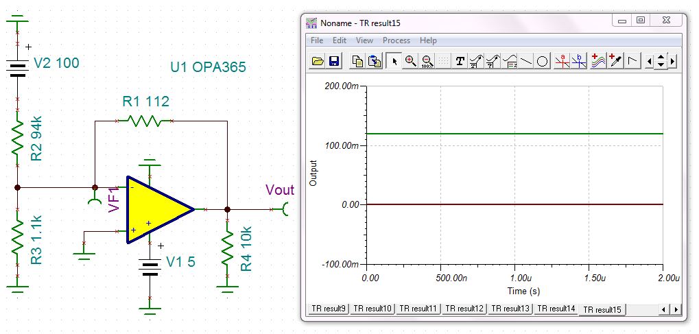
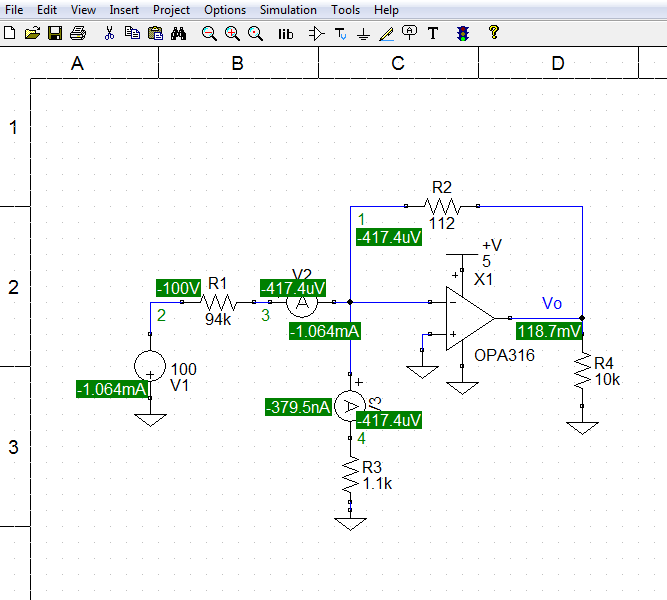
Below is my customer's simulation.

Circuit is same but simulation result are different.

How the above circuit acting and which simulation result is correct?

Best regards,

Alice

  • Hi Alice,

    A simple analysis of the circuit indicates that the operational amplifier output voltage should be about 119 mV, with V2 set to -100 V; so the TINA simulation is correct. Despite the presence of R3, the gain of the circuit is still -R1/R2, which is -112/94 k V/V, or 1.19e-3 V/V. Just to back that up, I simulated the circuit with TopSPICE and received the same result as TINA. I used an OPA316, instead of the OPA365, because I didn't have the OPA365 model in TopSPICE. That shouldn't make any difference in the outcome. You can see the TopSPICE image below.

    I am not familiar with the customer's simulator, but the circuit looks okay despite the incorrect output voltage. If the AD amplifier isn't in the simulator's library and the customer imported the model, they may have an internal pin connected incorrecly. Have they tried another op amp from the simulator's library in the circuit?

    Regards, Thomas

    PA - Linear Applications Engineering