This thread has been locked.

If you have a related question, please click the "Ask a related question" button in the top right corner. The newly created question will be automatically linked to this question.

ECG: Sharing One electrode for two instrumentation amplifiers

Expert 1110 points

Other Parts Discussed in Thread: TINA-TI

Hi,

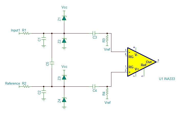
I have a circuit for measuring ECG and it is working perfect for one channel. I have one passive high pass filter (R1,C1) and one passive low pass filter (R2,C2) before the instrumentation amplifier. I am using only two electrodes, without RLD.

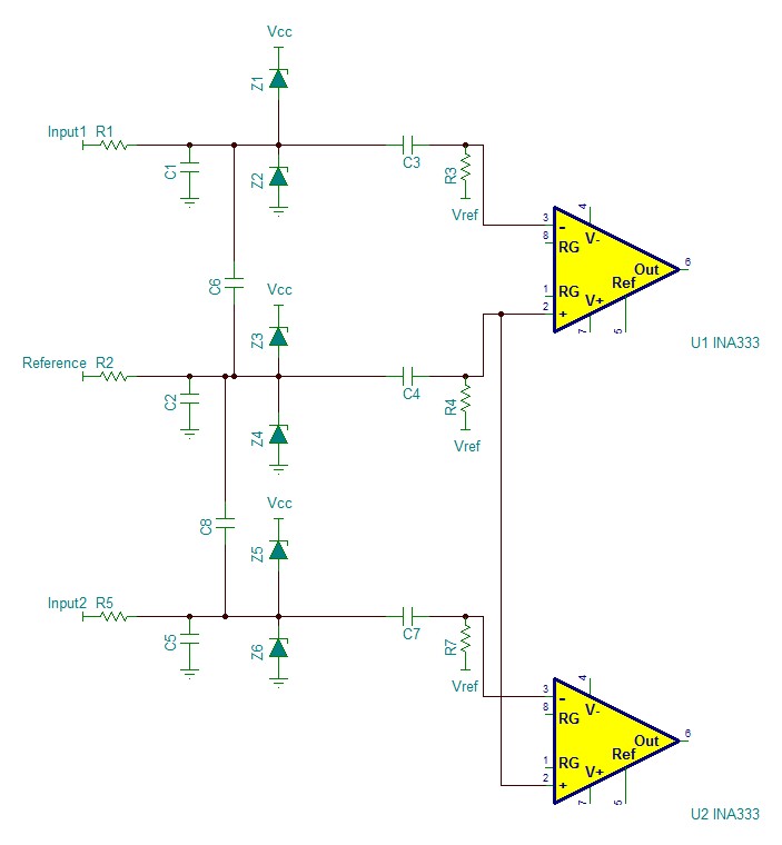
Now I want to have two channels with three electrodes, one as reference which is shared between two instrumentation amplifiers. What should I consider for sharing this reference electrode for two instrumentation amplifiers to keep the matching as good as before. Assuming that I have the same filter circuit as before with R1,C1,R2,C2 for reference electrode what changes should I make in the values of these components?

Regards

  • Hello V324O,

    Can you please upload your schematic?
  • Sure. Attached are two images one using two electrodes which is working well know, and another is the one with three electrodes. In the second image, one electrode is used as the reference electrode. What should I do with R2, C2, R4, C4, C6 and C8 to avoid mismatching? In the first case I simply chose them equal and as accurate as possible. But it seems that in the second circuit I have to have different values to keep the matching well.

    Thanks!

  • Hello V324Om

    Thanks for the schematic...it helps a lot.

    I have a couple recommendations. First, depending on the actual capacitor values, you may consider replacing some of the capacitors with X2Y capacitors (www.x2y.com). While I have not used them myself, from what I understand each X2Y cap contains 3 well-matched capacitors (2 common-mode and 1 differential). One of these capacitors would replace C1, C6, and C2 while a second X2Y would replace C8, C5, and C2. This would, however, make C2 twice the desired magnitude (there will be 2 X2Y common-mode caps in parallel), so you would have to reduce R2 by half to keep the same filter response. Of course this is only valid if the X2Y caps come in the values you need for your application.

    Secondly, I recommend running ac simulations to understand how the component tolerances affect the performance of the filters. Unfortunately TINA-TI does not support 'worst-case' or Monte Carlo analyses (you have to purchase a full version of TINA for that capability), though perhaps you could use parameter stepping to make things easier. I understand there are numerous variables which result in many simulations.

    On a side note, one trick we have learned is that for 'typical' results change the tolerance of the passive by 1/3 the maximum tolerance. This will yield a +/-1 sigma (or typical) result. For example, if your resistors are 1%, change their values by 0.33% for typical results. Of course for worst-case (+/-3 sigma), change the value by 1%.
  • Hi Pete,

    Thanks for your informative answer. Yes I know about X2Y caps, but I just didn't want to make it more complicated. Your are right, but my main problem is about choosing the right values for the components in the shared path between two instrumentation amplifiers. I mean theoretically. For example, following your suggestion, reducing R2 would result in the same frequency response but what would happen to the leakage current and common-mode rejection ratio? Doesn't it affect the CMR ratio?

    If we want to forget about X2Y capacitors, what values should I choose for R2, C2, R4, C4, C6 and C8 to have the best CMR ratio possible? I think it shouldn't be the same as the two other paths (electrode1 and electrode2).

    Appreciate your help!

    Regards
  • Hello V324Om,

    Thanks for the additional information.

    From what I understand of ECG, ac-coupling the inputs degrades the CMRR performance (please refer to Design Considerations for ECG Systems presentation at e2e.ti.com/.../2437.ecg-heart-signal-acquisition) especially due to the mismatch of the ac-coupling capacitor and reference resistor (C3, C4, C7, R3, R4, and R7 in your design). Therefore I would use precision passives for these component. Unfortunately precision capacitors can be costly. There are suggested component values in the presentation, though you may have to adjust them according to your filter requirements.