A related question is a question created from another question. When the related question is created, it will be automatically linked to the original question.
If you have a related question, please click the "Ask a related question" button in the top right corner. The newly created question will be automatically linked to this question.
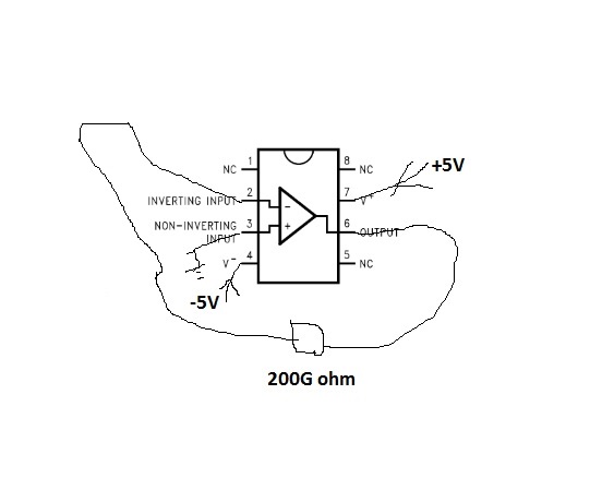
out put of LMC6001AI is saturated, what is the problem
At picoamp levels, the layout and design of the circuit is critical. It is very easy to create leakages in the pA's to nA's. The circuit needs to be clean and tidy, and not cobbled together on a solderless protoboard. Shielding and guarding will be required if you want any kind of accuracy.
Please see the following articles, as well as the Keithley Low Level Measurements Handbook (particularly chapter 2.1)
thank you very much for your advice. it is very helpful.
i checked the circuit and added two tantalum capacitors to the power supplyies, it seems the chip works well. i added -0.1V on a 100G ohm resistor, then the current was inputted into the inverting input and a 400G ohm feedback resistor is used. the output has a p-p noise of about 10fA, not bad.
meanwhile, could you please take a look at my new post " A question about LMC6001 amplifier, do feedback resistors affect each other?"