This thread has been locked.

If you have a related question, please click the "Ask a related question" button in the top right corner. The newly created question will be automatically linked to this question.

OPA 836 for low temperature, low noise circuit

Other Parts Discussed in Thread: OPA836

Hi there,

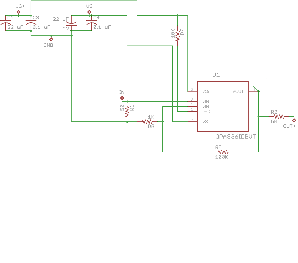
We would like to design some circuits with OPA 836 work at temperature below 1K and (hopefully) input noise below 4 nV/sqrt(Hz). The circuits have been built and tested and we saw a few issues. First of all, the circuits works at V+ = 0.8 V and V- = -0.8 V when using dual supply which is a bit lower than the nominal +/- 1.25 V. When we say "works" we mean it can amplifier the source (the gain is temperature-dependent). However, as temperature goes down, we have to increase the power to +/- 1.1 V (T = 77K). This may due to the temperature-dependent of the transistors in the op-amp. And it's still below 1.25V. What's interesting is that once we apply V higher than +/- 0.8 V it starts to generate garbage. So we would have to apply a vary narrow voltage range for each temperature. 

Would anyone take a look at the simple design and give us some ideas? 

Thanks,

John

0.png

  • The circuit is basically the same as the OPA836DBV test board. And the resistors are thin film.
  • Hi John,

    Are you sure you want to make the OPA836 work close to T = 1K or -273.15'C? I think you could make the OPA836 work at lower supply voltage and amplify and make it to "work", but the parameters won't be guaranteed as specified in the typical characteristics table of the datasheet. 

    The OPA836 is built on SiGe process and usually the transistor stops behaving like a transistor at about 100-110K, due to very low emitter-base current injection efficiency. I don't think the OPA836 can be used for what you are doing. I would suggest you to look at pHBT process that could go to cryogenic temperatures using special band-gap reference circuits, but I don't think none of the commercially available pHBT parts could go as low in temperature as 1'K. This is something which you will have to build in-house.

    Best Regards,

    Rohit   

  • Hi Rohit,

    We are sure we want the OPA836 to work below 1K. We realize that it's way off the working temperature but it turns out that it "works" at about 2K. When we say works we mean it amplifies. We haven't had a chance to test the noise level. Usually the input noise will decrease substantially with temperature since it's Johnson noise.

    We didn't quite sure why it works but increasing the power supply seems to compensate the emitter-base current lose? The fact that we need to increase the power supply to make it work for lower T may support that idea.

    John

  • Hello John,

    Increasing the power supply would have to do with compensating for the negative temperature coefficient (-2mV/'C) of transistor Vbe or turn-on voltage. The collector current for the transistor is provided by Ic = Is*e^(Vbe/Vt), where Is is the saturation current and Vt = kT/q. With reduction in temperature for a fixed supply, the Vbe for a transistor turn-on increases while Vt reduces which causes the Ic to reduce. In-order for Ic to remain constant with reduction in temperature, the increase in power supply would bias up the transistor higher and thus compensate for the increase in Vbe.

    When you mentioned that you are getting garbage data when you increased the supply voltage from +/-0.8V to +/-1.1V, what do you mean by garbage data? Could it also be that while you are cooling down the ambient temperature, the OPA836 part has not cooled down sufficiently enough to the same temperature as the ambient? How long are you operating the OPA836 at T = 77K before it starts to output garbage, and how are you measuring the temperature that the OPA836 is at? Are you using a thermocouple to measure the OPA836 package temperature?

    Best Regards,

    Rohit

  • Hi Rohit,

    The output of the OPA836 is monitored by an oscilloscope and when I say it's "garbage" I mean the amplitude of the waveform is out of the scale and with very high frequency harmonics. By the way, we are using 10 kHz.  It's also important to note that this happens even at ambient temperature - before I cool it down. 

    The circuit is mounted tightly on to a PPMS sample puck to ensure good thermal contact. The cool down rate is sufficient slow so that it reaches quasi-equilibrium for each cooling step.  The output signal is monitored while it's cooling. The whole process takes about 1 hour. The PPMS has built-in Ge thermometer for measuring the temperature down to cryogenic temperature.

    Thanks,

    John 

  • Any idea on why the V+/V- are in such narrow range whereas it should be between 1.25-2.75 V as specified in the manual? 

    Thanks,

    John

  • Hi John,

    I would expect it to work normally at ambient temperature with the supplies specified in the product datasheet. What is the supply current that you are recording for the part? If the amplitude of the waveform out of scale and you see very high frequency harmonics, are you noticing any jumps in the supply current? If yes, then there is a possibility that the part is oscillating. Also, is there a possibility that you can attach a picture of the schematic? Are you using inverting or non-inverting gain configuration for the OPA836?

    Best Regards,

    Rohit

  • Hi Rohit,

    The supply current is about 1 mA when we power it up using V = +/- 0.8 V. The input amplitude is about 10 mVpp and we set the gain to be 100. It doesn't seem to have any jump in the supply current. I attach the schematic circuits on the following, I guess there are two issues, 

    1, is the gain too big? 

    2, the VS- and the output pin seems to go under the OPA836 itself and it could cause potential capacitive coupling? We are still working on the design of the circuits. Any suggestion?

    Thanks,

    John

  • Hi John,

    It seems that Rf value being used is too high close to 100k. It is recommended in the datasheet to restrict the value of Rf to 1kohms for gains higher than 1V/V. OPA836 shows significant peaking with Rf ~100kohms just for gain of 2V/V. So, I would expect it to be oscillating at 100V/V gain with Rf ~ 100kohms. Is it possible that you can make Rf = 1kohms and Rg = 10ohms for a gain of 101V/V and try running at +/-1.25V, to see if it does not give high frequency harmonics?

    Best Regards,

    Rohit

  • Good point. We are searching for some 10 Ohms thin/metal film resistors which has the same temperature coefficients with the 1k Ohms resistor. We can work around that, I think. Those resistors should be made from the same materials such as Nichrome. I'll keep it update once we has process on that.

    John