This thread has been locked.

If you have a related question, please click the "Ask a related question" button in the top right corner. The newly created question will be automatically linked to this question.

OPA output inversion during input overdrive

Hi,

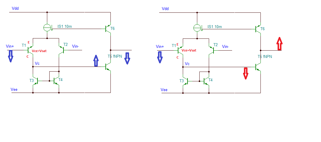
The example below shows the case where the input is being driven about 0.5V below the negative supply rail. The output level inverts momentarily from the negative rail to the positive rail. The duration of the output inversion worsens the more the input is overdriven.


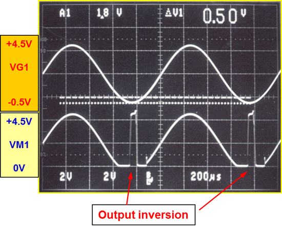
Q1: Why there would be an output inversion when the input is overdriven?

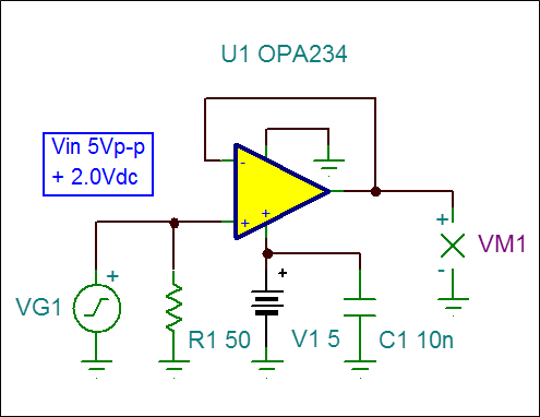
Q2: In the Tina simulation, the simulation results don’t show any abnormality, is the OPA model not accurate enough?  


Many thanks and look forward to your reply!


Best regards,

Bell

  • Hi,

       From the data sheet (www.ti.com/.../opa2234.pdf) page number 2, you are violating common mode input voltage range. In the data sheet it is given that minimum value of input common mode voltage is -0.1 V. When your input goes below 0 V , you will be violating it.

    Regards

  • Hi Deepak,

    Thanks for your answer.
    It's clear that the Vin is beyond the common mode input voltage range. I am just wondering why output will invert when the input is overdriven. Could you give more details on this?

    And why the TINA simulation results don’t show any abnormality?

    Best regards!
    Bell
  • Bell,

    Below please see a simplified op amp schematic of OPA234. The reason behind a phase inversion has to do with the fact that in a normal operation emitter, Ve, follows the input, Vin, but collector of the input transistor, Vc, should be always 180 deg out of phase with the input - this is only possible when Vce>Vsat.  As the input Vin+ is pulled down, Vc goes up and output goes down - as you would expect (see schematic on the left).  However, when you overdrive the input below a negative rail, the voltage between a collector and emitter get smaller to the point that Vce=Vsat and Vc cannot move up (out of phase) with the input and thus gets dragged down causing the phase inversion you see on the schematic on the right below.

     Tina simulation model uses greatly simplified circuit and is meant to show only linear operation of OPA234.

  • Hello Marek,

    Thanks a lot for your answer.
    I have set up a circuit as what you show above. The simulation results matches well with the analysis.
    Thanks again for solving this problem.

    Best regards!
    Bell Ye
  • Glad I could help.