This thread has been locked.

If you have a related question, please click the "Ask a related question" button in the top right corner. The newly created question will be automatically linked to this question.

Reducing INA199A1 noise in existing design

Other Parts Discussed in Thread: DRV8838, INA199, INA333

Hello,

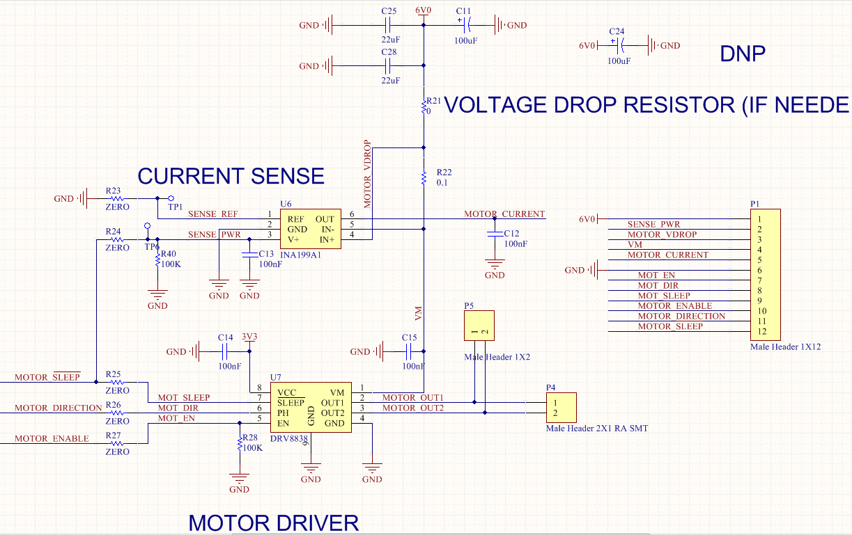
   I designed in the INA199A1 which uses a 0.1 ohm shunt resistor from a 6V rail which then feeds the input of a DRV8838. This is used for measuring the current going to the motor attached to the DRV8838. This is an existing PCBA, and I'd prefer not to modify it more than i have to. Nominal current to measure is 100mA.

   The INA199A1 has a 0.1uF decoupling cap on the V+ input, and also on the V- input. The 6V rail which powers the INA199A1 has 2x 22uF caps which are within 10mm of the '199.

   The problem is that we're getting a lot of noise on the output of the INA199A1. The output of the INA199A1 has a 0.1uF cap to GND for filtering. Can I increase this cap to add more filtering, or will I need to cut & jump to put a series resistor between the output of the '199 and the cap?

Thanks,

Derek

  • Hello Derek,

    Can you please share with us your schematics? or at least the block that concerns the INA199.

    Best regards,
    Amjad
  • Hi Dereck,

    1)It is out of specifications to add too much capacitive load on the output of the INA199, max cap load is 1nF, here is a crop from page 3 of the datasheet:

    2) Can you take off the C12 cap and take a scope of the "differential input" VS "output" VS "V+ supply" and share it with us?

    3) When filtering is needed in current shunt monitors, it has to be placed in the input to remove high-frequency noise between Vin+ and Vin-. The figure 8 shows the recommended design and values for the filter. If the filter is needed, use the lowest possible series resistance and a ceramic capacitor. Recommanded values for this capacitor are 0.1uF to 1uF. In many cases a filter is not needed.

    I hope that this helps,

    Best regards,

    Amjad

  • Adding a filter on the input would require extensive cuts & jumps. Remember, this is an existing PCBA. Can I filter the output using a resistor before the capacitor? That would be easier.
  • Hi Dereck,

    I understand that you can't do cuts & jumps. I would say yes you can add a resistor before capacitor to isolate the capacitive load and filter, but first I can't tell you what values as I don't know the nature of noise that you get, and secondly it's not a best practice because if the noise comes from the input then it will be amplified in the INA which will affect your accuracy.

    Can you take off the C12 cap and take a scope of the "differential input" VS "output" VS "V+ supply" and share it with us? Maybe I can help you more.

    Best regards,
    Amjad
  • Hi Dereck,

    Any news with your design?

    Best regards,

    Amjad

  • I added a 1k ohm resistor between the output of the INA199A1 and the output capacitor, to form a LPF with 167Hz cutoff. I'm also building a tiny filter PCBA to fit inside that does this with a Butterworth filter.


    How do you compute the corner frequency of the input filter shown in the datasheet? The datasheet just says to use Rseries < 10 ohm. What values are recommended to get a corner frequency of 100Hz? 1000Hz?

    --Derek

  • Hi Derek,

    Fc= 1/ (2 * Pi * R * C ) assuming that you choose the same R in the both sides. Always have R < 10 ohm, because higher value contributes to the DC error.

    Best regards,
    Amjad

    Please be sure to mark the thread as answered if your question was answered
  • Hi Amjad,

    I saw that your equation is "Fc= 1/ (2 * Pi * R * C )". But I got the difference equation. Would you help to check which one is correct?

    BTW, I have fine-tuned the Cdiff value and can get the difference result. As I know, the key difference is the Fc, but which one Cap value is be recommend? Why?

    Thanks!

  • Dear Jerry,

    You are correct with the difference equation. If you follow the link below and reference page 53, you can see the formulae for an input filter stage (INA333 instrumentation amp used in the reference).

    www.ti.com/.../slyw038b.pdf

    As Amjad pointed out, if you choose the same value resistor for each side, and eliminate the common mode capacitors, the equation simplifies to

    f_diff = 1/4*pi*R*C

    Finally, as for what value of capacitor to choose, we recommend that the resistors be less than 10 ohms, so you can then calculate your needed capacitor based on the nature of your input signal. If the signal is DC, then you can select a fairly large value capacitor, as you only care about the DC portion and can remove any other unwanted noise. In short, the cap you choose should be based off of what signal you plan to input to the device.