This thread has been locked.

If you have a related question, please click the "Ask a related question" button in the top right corner. The newly created question will be automatically linked to this question.

Suggestion for High-Speed Rail to Rail Op-amp

Other Parts Discussed in Thread: LM741, THS4304, THS4221, LMH6702, OPA659, OPA2674, OPA2695, OPA695, OPA3690, OPA2690, TINA-TI

Hi everyone,

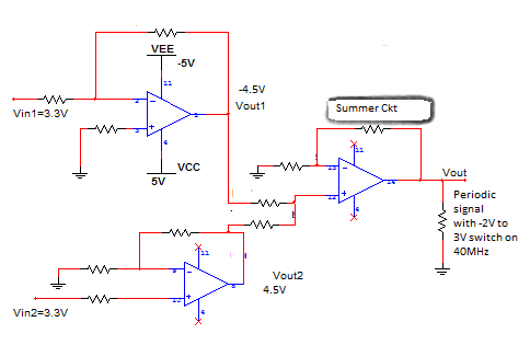
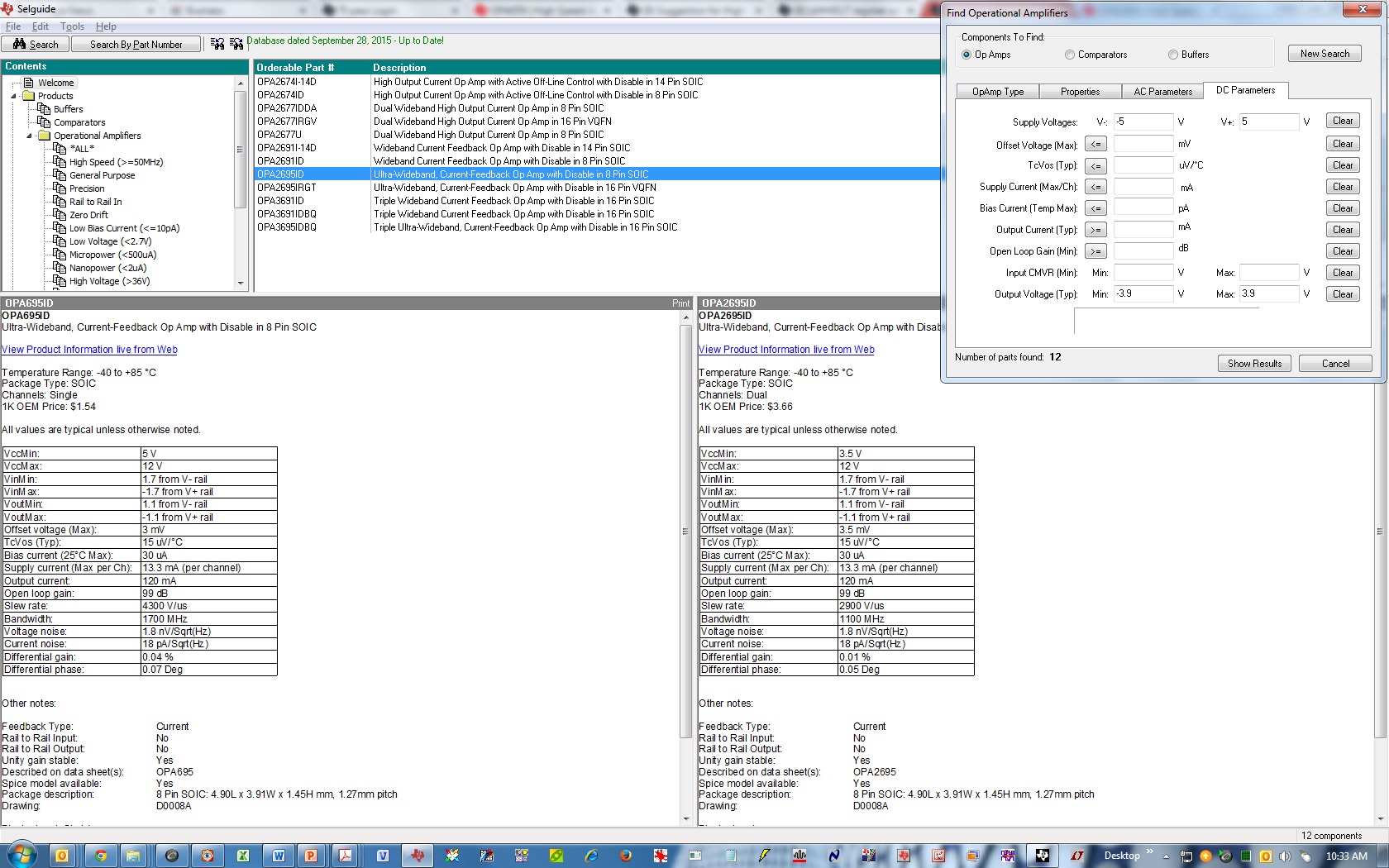
I am currently having the schematic for switching circuit which is being used in lower frequency with LM741. But, now I want to shift the switching application to the higher frequency about 40 MHz. Even I have calculated slew rate required for my application is around 2000V/us. I also want the amplifier to be switched from -5V to +5V in the output.

All suggestion are welcome for selection of particular application.

Thank you.

Regards,

Abhi

  • Hello,

    I could not find any Rail to Rail output op-amp with 2,000 V/us slew rate. The closest would be the THS4304 (790 V/us, 3GHz GBWP) when I search in Selguide.

    THS4221 is another possibility (990 V/us) if you can accept an output swing to within 0.3V of either supply rail (i.e. +/-4.7V with Vs= +/-5V).

    The LMH6702 slew rate (3,100 V/us) is more than what you need, but its output voltage swing is 1.5V from either supply rail (i.e. +/-3.5V with Vs= +/-5V).

    The OPA659 and OPA2674 also have high enough slew rate, but are not exactly rail to rail output either (they swing to within 1V of either supply rail).

    Regards,

    Hooman

  • Thank you Hooman for your reply.

    I would definitely go through all datasheet, which you have suggested.

    But, when i go through my application the input voltage would be switched from 3.3V to 0V.  It has to operate on 40 MHz. Also it has to switched from rail to rail of +-5V (Vs). So we can let go higher GBWP cause it won't need higher gain at higher frequency.

    Can you suggest me any op-amp regarding this updated data?

    Thank you.

    Regards,

    Abhi

  • Hello Abhi,

    I'm not entirely sure what you are describing in words. I think a schematic or block diagram would be much better, if you can attach it here.

    Regards,

    Hooman

  • Hello Hooman,

    Sorry if I could not made you understand my application. Here, I am attaching the schematic with op-amp still to be decided. It is being utilized with lower frequnency. So I am assuming it should work for the higher frequency as well. Vout of the summer ckt must be -2V low and 3Vhigh with definite 40MHz.

    It would be very kind of you if you could help me out.

    Thank you.

    Regards,

    Abhi

  • Hello Abhi,

    The list of high slew rate op amps that I gave you earlier still stands. One possibility is that if you can raise your +/-5V supply voltages higher, then you'll have more devices to choose from that have high slew rates (e.g. OPA659, and OPA2674 are good examples) because you will eliminate the requirement of having to swing close to the supply rails.

    Here is a design which TI Webench produces when you want to raise your 5V supply to 6V for this purpose with about 50mA output current capability:

    You would need to do something similar for the -5V supply to produce something like a -6V supply instead to run the devices (Webench can probably be used for that design as well).

    Regards,

    Hooman

  • Hello Hooman,

    Thank you for the suggestion about Boost converter. By going through the datasheet of OPA659, i found that the output voltage swing is +-4.8V which is more than i required. I also check in the datasheet that it can provide Vo=6Vpp with the comparatively lower rise and fall time, which are suitable for my application.

    Also the point to be mention that in the specification it mentioned about Vo=4.8V at No load and Vo=4V at 100 (Ohm). My load is capacitive with 400pF (max). Would it affect the level of output voltage? Would it increase or decrease the output voltage?

    Thank you again. 

    Regards,

    Abhi

  • HIi Abhi,

    The OPA659 output swing of +/-4.8V is with Vs=+/-6V. With your +/-5V supplies, you will be limited to +/-3.8V.

    With a capacitive load, the only output swing impact would be the device output current limitation when dealing with large swing across a large capacitor (ic= C * dV/dt).

    BTW, I am currently travelling till next Monday and my responses will be delayed.

    Regards,

    Hooman

  • Hi Hooman,

    Thank you for your help.

    Can I use somekind of LDO (Voltage regulator) for particular 6V supply generation? So that I won't require to use Boost converter in my circuit. 

    One more thing have a pleasant journey.

    Thank you.

    Regards,

    Abhi

  • Hi Abhi,

    You can use an LDO to produce +/-6V supplies, if you have positive and negative sources >6.5V and < -6.5V respectively, because an LDO requires a certain minimum drop out voltage (usually at least 02V). I recommended a switching boost circuit because I had thought you only have +/-5V available to you.

    Regards,

    Hooman

  • Hi Hooman,

    Thank you anyway for the Boost converter ckt. I will consider that in my future project.
    But, as OPA659 is single channel op amp can you suggest me to multiple channel channel with comparable parameters from TI? As you know I have to implement adder ckt in the final stage, would require more than one op amp.

    Regards,
    Abhi
  • Hi Abhi,

    The OPA2695 (dual) has many of the characteristics of the OPA695, as the Selguide image below shows how they compare:

    Regards,

    Hooman

  • Hi Abhi,
    If you must have a traditional voltage feedback device (OPA2695 is Current Feedback), then I suggest the OPA2690 (dual) or the OPA3690 (triple).

    Regards,
    Hooman
  • Hi Hooman,

    Thank you for your suggestion.

    One more thing I would to ask that is there any kind of equation or relation between Rs to the Capacitive load? From the datasheet I have came across the Graph for Rs Vs. Cload.

    Thank you.
    Regards,
    Abhi
  • Hi Abhi,

    Here is a good application note from Soufiane on capacitive (cap) load driving and resistive isolation:

    The resistance in series with the output to compensate for the load capacitance is intended to preserve phase margin due to the phase shift that the cap load causes. The optimum value of the series output resistance is dependant on several interdependent factors (i.e. device open loop output impedance, its open loop gain / response over frequency and its phase margin).

    I think bench measurement and the datasheet plot of the series R vs. CL are the best methods to go about the task of fine tuning such a circuit.

    Regards,

    Hooman

  • Hi Abhi,

    Here is one way to predict the isolation resistor OPA2690 needs for a given cap load using TINA-TI simulation.

    I've used the OPA2690 model in simulation and used a large L and large C to open the loop and look for phase margin.

    For the simulation shown below, I've done the following cases:

    CL= 100pF

    Series Isolation resistor (ohm)        Loop Gain 0dB frequency (MHz)          Phase Margin (deg.)

    0                                                               91.3                                                              15.8

    10                                                             91.4                                                              34.9

    20                                                             95.3                                                              46.7

    50                                                             87.3                                                               60.5

    So, 50ohm or 20ohm are good resistor values to use (based on the simulated phase margin).

    Here is the TINA-TI file for above:

    OPA6290 cap load isolation resistor open loop analysis E2E 10_8_15.TSC

    Regards,

    Hooman