This thread has been locked.

If you have a related question, please click the "Ask a related question" button in the top right corner. The newly created question will be automatically linked to this question.

LMV931 Latch-up?

Hi,

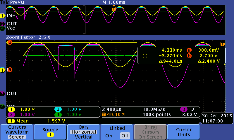
we are using LMV931 RRIO opamp to buffer a signal. The fb loop is closed remotely through a cable. It appears that when we open the loop (bad contact) some will latch-up near rail (4.4V at supply 5V) and never recover once the loop is closed back. Since the opamp is RRIO (200mV above supply)  I would have assumed that even if opamp is forced to saturate near rail when loop is opened, it would not latch-up and recover once faulty condition is removed. The vast majority that have seen will recover though, but we have some samples that will not.

Anyone can help understanding the issue?

Thanks,

JR

  • Jean,

    Can you provide the full part number (with package code)
  • Yes:

    LMV931Q1MF/NOPB

    Parts confirmed with part marking.
  • Hi Jean,

    Please provide a schematic, including the input drive signals and output loads.

    Does normal operation return when the power is cycled? Is the LMV931 damaged?

    Is the LMV931 drawing excessive current (or getting hot?). Did you look with a scope to see if it was oscillating? Does the feedback go through a cable or other connector that is disconnected?

    If the feedback is opened, the output should "rail" to V+ or V-. The output staying at a particular voltage would be unusual. There is some other factor at work here...

    Would slamming the output to the rails cause issues with the load? Is it inductive?

    Normally when a "remote sense" configuration is used, a high-value resistor is placed across the remote feedback path to maintain local feedback in case the remote feedback path is broken, preventing wild swings in the output.

    Try placing a high value resistor (10k to 1Meg, depending on your circuit impedance) across the output and incoming feedback lines and see if it helps.

    Regards,
  • Hi Paul,

    here is a part of the circuit:

    Does normal operation return when the power is cycled? Is the LMV931 damaged?

    --> Not damaged, returns to normal operation after cycling.

    Is the LMV931 drawing excessive current (or getting hot?). Did you look with a scope to see if it was oscillating? Does the feedback go through a cable or other connector that is disconnected?

    -->  Not excessive, not hot either. No oscillation. Yes, thru a connector, see schematic.

    If the feedback is opened, the output should "rail" to V+ or V-. The output staying at a particular voltage would be unusual. There is some other factor at work here...

    It indeed rail to V+, but never returns to normal after, that is the point...

    Would slamming the output to the rails cause issues with the load? Is it inductive?

    --> Apart than the cable, this is purely resistive.

    Normally when a "remote sense" configuration is used, a high-value resistor is placed across the remote feedback path to maintain local feedback in case the remote feedback path is broken, preventing wild swings in the output.

    Try placing a high value resistor (10k to 1Meg, depending on your circuit impedance) across the output and incoming feedback lines and see if it helps.

    -->  Well, we don't have a "backup" resistor for that, thought we would be safe with a RRIO , but anyway, I did try with 100k and it does the same thing. I have to get in the range of the normal to get correct behavior... BTW, I don't see any overshoot over 5V when I connect live the cable, this is fairly low current and short cable. 

    Thanks

    Jean


  • Hello Jean,

    Hmm. Yes. This is strange. It should recover immediately. The impedance are low and it is a RR input device.

    Please confirm that your input is 1.25V (2.5V/2) and your supply is 5V.

    Is there *anything* else connected to the output or the feedback line? MOV's? Diode Clamps? Caps? What is the ambient temperature? What is the failure rate you are seeing? Are they the same datecodes? The datecode is marked on the *bottom* (belly) of the package or on the reel/box.

    Are you measuring with a scope or DMM? Just want to make sure it is not oscillating in the 4.4V range (it is still possible for the output stage to oscillate - even with a big differential on the inputs).

    The LMV931 is bipolar, so the supply current will increase a few percent when the outputs are railed. Would that cause any issues with the supply? Is the supply from a battery, zener or regulator? What bypass capacitors do you have? Are they close?

    Have tried other op amps? Just to rule out some weird layout/fixture issue? Unfortunately, there are no other TI devices with the same SOT-23 footprint, so you may need to try the On Semi version if you have a dedicated layout.

    If you are still in the breadboard stage, try the OPA314AIDCK (SC-70 version) and *stretch* it to the SOT-23 pads.

    I'll take a look on the bench and see if can duplicate the issue.

    Regards,
  • Hello Paul,

    input is really 1.25V. This is fed by a current sensor that has no current at this moment, so its the middle point : 2.5V/2.

    The schematic I have post is really the circuit on the board. On the other side, this goes  to a load resistor that closes the feedback and a reading is taken across that resistor in differential. I have only seen this once on hundreds of boards, but this is not something I had included in the production line testing, so there could be more latent fail... I don't have the date code as I do want to alter my only failing circuit, I do not have the reel either, this was assembled at out CM.

    All measurements were done at oscilloscope at 25 degC, no oscillation visible. This goes straight to the rail and never come back. 

    The supply is stiff, I have a bulk 10uF for the board and each opamp has 100nF decoupling, very close.

    No, I didn`t try another opamp since this is the first time I see this on hundreds of boards we have shipped with the same opamp.

    My feeling is that I will have to send you the board or the opamp for you to test. Meanwhile, I think I will ask a new test on the production line test just in case....

    Thanks 

    Jean

  • Paul,
    I have unsoldered the IC and I have the batch code, I don't know if it's of any help. This is lot number 495 .
    Thanks,
    Jean
  • Hi Jean,

    We need the full part number for our secret decoder ring.

    Also, there are two versions - the "TI" version and the "National" version - we need to know which one.

    Regards,
  • LMV931Q1MF/NOPB
    Part marking : ALAA
    However, I cannot say if it's National part, but it was initially created here as a TI part, so I would presume that it's the case.

    Thanks

    Jean
  • Hi Paul,

    I am a colleague of Jean and we have recently encountered problems with the same op-amp that are similar (but more subtle) to the one Jean is describing. We have managed to reproduce the problem when the following steps are executed :

    1. Power up the board (Vcc = 5V) and let the input of the amplifier rise to its idle value (2.5V -> IN+ = 1.25V)
    2. Disconnect temporarily the feedback loop and reconnect it
    3. Lower the input voltage down to ~1.5V (IN+ = ~0.75V)
    4. => Output of the op-amp saturates to Vcc

    This is a similar problem but more subtle since it happens at an input voltage that the op-amp only sees at specific points of operation of our final (shipped) product. In other words, we have not been able to prevent boards with op-amps behaving as described from being shipped to customers (we have had at least 2 cases of failures at customer site that appear to have been caused by this problem, and there are probably other latent boards that will cause failures in a near future).

    I have made a video that clearly shows how the problem can be reproduced :

    I will be desoldering the op-amp tomorrow to get its datecode. This is a major issue for us since it is affecting directly our customers (and our reputation by the way). We will be waiting for your input for the next steps (do you want to get the op-amp shipped back to TI under RMA?).

    Regards,

    Marion Nourry

  • Hi Marion,

    Thanks for the video; it does a great job showing the problem.
    It looks like an inversion problem in the small input range (0.73V and 0.81V) after a trigger event (railing the output when feedback is open) and has a reset event (under 0.25V Vin)

    I think the next best step is to send us some of the parts that exhibit this unexpected behavior to look at in our lab.
    Will contact you through Amanda for more details on top mark for lot tractability for all the affected parts you see 

    Please ship the parts to my attention:

    Karim HamedTexas Instruments (SVA)
    2900 Semiconductor Dr., Santa ClaraCA, USA 95051

    Regards,

    Karim

  • Leonard,

    Per your email request, I will add my input.

    When the loop opens the differential input voltage will exceed data sheet limit of 200mV.
    Diodes in the input stage will conduct. It may be difficult to regain normal operation.

    What is the DC voltage on all pins during the open connection?
    What is the DC voltage on all pins during the re-connection latch?
  • Ron,

    I have tested the LMV931 with loop opened and it seems there are no diodes between In+ and In-, but only against the rails.

    The spec says that diff range is V- to V+.

  • Jean,

    Yes, you are correct.
    I misread the text.
  • Karim,

    it seems opening the loop is not mandatory, I was able to get the same result with an offsetted sine wave (1 khz)  at IN+ input. The real trigger is to saturate the output, I think. If I repeat this test on a working board I get an expected result ( a clipped output which returns to normal).

    What is the overload recovery time, may that be the issue here?

  • Hello Marion and Jean,

    Excellent Video! Thank you! This helps a lot!

    We do not expect this behavior. This is strange.

    I have received your failed device. We will be submitting it through the QTS channel for analysis. They will do the electrical tests and FA on the device. This will take a week or two to get preliminary results, and a bit longer for a full report.

    In the mean time, we would suggest trying a LMV321-Q1. The pin out is the same and should drop into place. It is not R-R input, but you do need need R-R input since your highest possible input voltage is 2.5V (typ 1.25V).

    Regards,