This thread has been locked.

If you have a related question, please click the "Ask a related question" button in the top right corner. The newly created question will be automatically linked to this question.

High Side 6 decade current measure

Other Parts Discussed in Thread: TIPD135, TIPD156, TIPD175, PGA206, TIPD129, INA111, INA141

Dear Engineers


Herein the description of my problem


I have to design a high side current monitor with the following specs:

6 decade log scale current measure: from 100nA to 100mA

1 MHz large signal bandwidth

10% of accuracy in the log scale


I need to measure the current which flows from a regulator to a microcontroller VCC pin (ARM core). Of course the microcontroller power pins is filter with a 10nF -100nF capacitor. The microcontroller can operate in power down mode Idd = 100nA up to 50-70mA operating current at full speed. The filter capacitor creates a lot of problems in the current measure as well has the wide current measure range and bandwidth.

I’m exploring different approach. For example:


  1. Log element inserted in a closed high gain loop using and High current OP amp


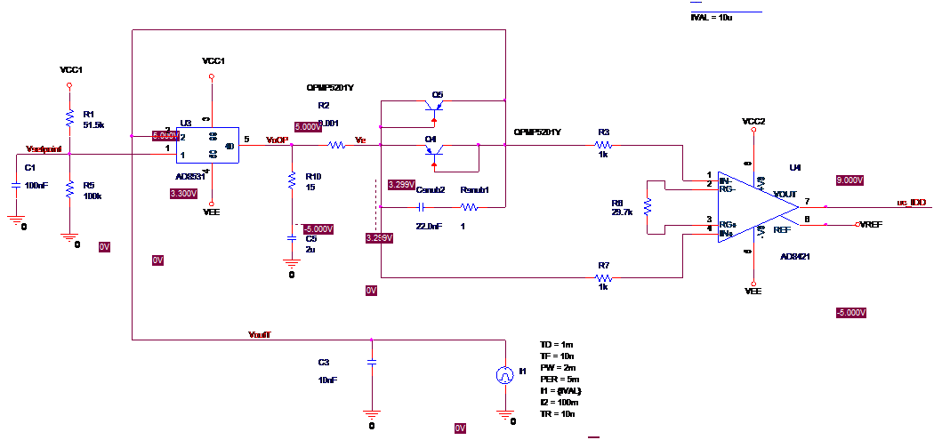
A OP high speed power amp with a diode which acts as a log element (VBE and IS temperature an compensation is done with a different section of the circuit Q4, C5 are matched BJT and matched also with other BJT used in the compensation section of the circuit, not shown here)

In this case because the non linearity of the loop, it is impossible to get good dynamic performance with different current level. The ub_IDD signal is connected to a high speed 10 bit ADC  


B ) Log element inserted in a closed high gain loop of and Linear regulator


Similar problems, difficult to get good dynamics performance because the presence of the out capacitor which creates ringing and of the Q4 diode (BJT) which is a not linear in a loop


So I decided to divide the problem in 2 sub problems:

A linear section which convert the current to a voltage, followed a group of  different amplifier blocks connected in parallel with different gains to cover 6 decades (U11 gain  =1, U12 gain = 10, U13 gain = 100 all High impedence, high speed OP amp).


The idea is shown below:


The difficulties here are:  


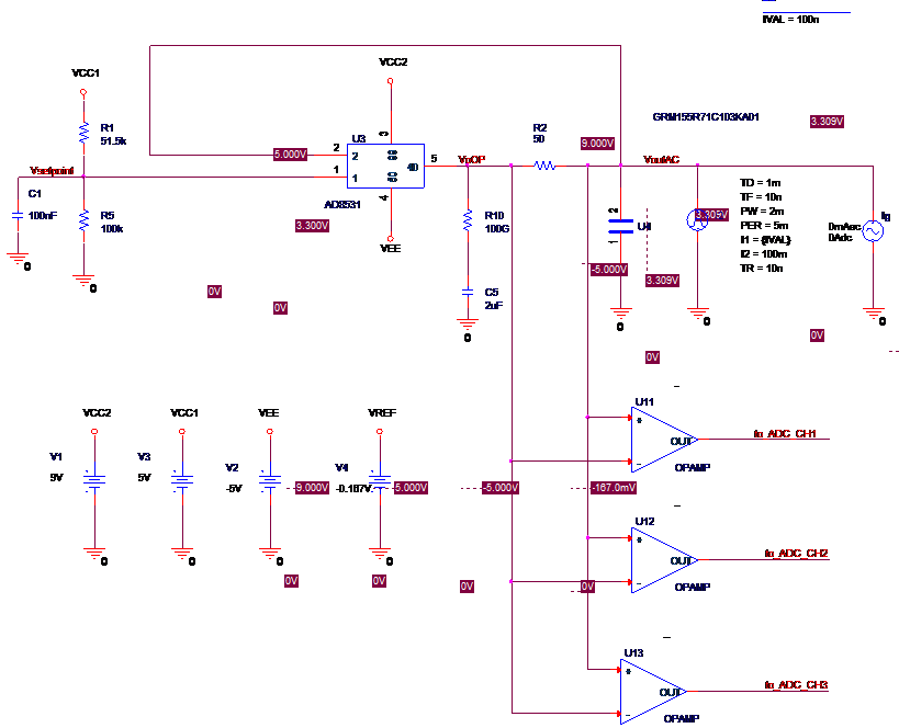
  1. the presence of the output CAP U4 (10nF) which create an additional pole in Gloop (ringing), same as above, but now the non linear element is not present.

  2. the wide range of the voltage drop on R2 (5uV to 5V), difficult to measure due to the input amp noise, howerver the temerature compensation of the non linear element is not anymere necessary


Do anybody suggest any other idea or any ready to use device?

  • Paolo,

    I cannot see your schematics. You and try to repost or you can email me directly at j-contreras@ti.com

    Thanks,
    Javier
  • Dear Javier

    Yes just done

    Regards

  • Hello Paolo,

    Detecting such a wide range of current is definitely challenging, especially given 1MHz BW. The options we typically see are either changing the gain of the device (e.g. using a PGA as in TIPD135) or switching in different sense resistors (or perhaps a combination of both). Though I typically advise against using multiple sense resistors, it's likely you'll have to do so because of the load current range and subsequent sense resistor voltage drop. I recommend using 4-terminal resistors to make PCB layout easier.

    Unfortunately we don't have a good instrumentation amplifier solution for this application due to the BW requirement. The closest devices that you may want to take a look at are the INA111 and PGA206/7. If low-side sensing was an option, a wider BW op amp could be used. The only other option I can think of is to perhaps build your own difference amplifier as was done in TIPD175, but use it on the high-side. One concern is the input resistors. They must be sufficiently large with respect to the sense resistor(s) but larger resistors introduce additional noise. In addition, the discrete difference amplifier approach will have degraded CMRR due to the external resistor matching and poor drift (if temperature changes are expected). If you can perform a 2 point calibration as discussed in TIPD129 and TIPD156, you could greatly minimize all gain and offset errors. Errors associated with temperature, however, will still be present.
  • Dear Pete

    Thanks for you suggestion. At the moment I found the way to cancel the ringing at the out of the OP amplifier even if connected to relative high Cap (100-300nF), see last schematic in my first email. So it is possible to measure the  voltage across to R2 with a block of parallel amplifier. However I have to find and op with  able to amplify a small signal of 5uV in 1MHz bandwidth with high input Impedance. May you suggest any TI part ?

    You also suggested to switch different resistors. I evaluated this approach, however I see problems like the fact that switches have leakage currents, as a limited isolation at 1Mhz. Furthermore, even using an OP to cancel the voltage drop on the resistor (see last schematics), I would need a 50ohm resistor for 100mA max current to limit the voltage to 5V, and 50KOhm resistor for the 100nA measurement. Again this approach is similar to introduce e diode in the loop. With the highest resistor the dynamic of the loop degrade, and the bandwidth collapse.

    Regards

    Paolo

  • Hello Paolo,

    Our lowest offset instrumentation amplifier has an initial input offset voltage of 25uV+(75uV/G), which is greater than the offset you're trying to measure. So, no matter what, you will have to calibrate out the offset to use one of our instrumentation amplifiers.

    You may want to evaluate the INA141. The bandwidth is listed as 1MHz, but please note that this is a typical specification and can vary by approximately +/-20% over process. The offset voltage is 100uV (Max) in a gain of 10V/V. Please note that the INA141 has an internal gain-setting resistor, so there are only 2 gains for the device: 10V/V (Rg open) and 100V/V (Rg shorted).

    Good to hear you found a solution to the ringing.

    Hope this helps!