This thread has been locked.

If you have a related question, please click the "Ask a related question" button in the top right corner. The newly created question will be automatically linked to this question.

INA321 reference

Other Parts Discussed in Thread: INA321, LM358, TINA-TI

Hello, 

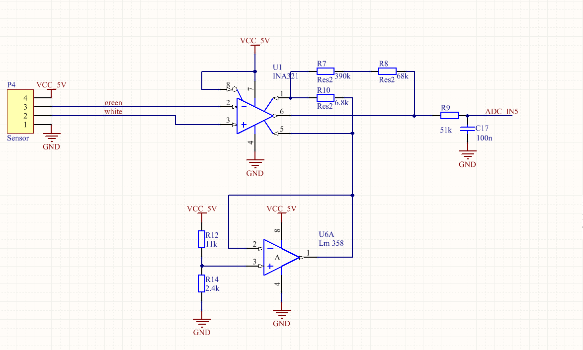
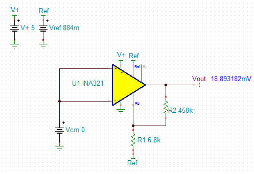
  I am using the INA321 amplifier to amplify the signal coming from a pressure sensor. The reference is set by a LM358 operational amplifer and is equal to ~884mV. The output is filtered by a simple RC high pass filter. If the voltage on the input is 0mV the output should be the same as reference (884mV), but unfortunately I get 0mV. If I attach the sensor the gain (which is 342, set by resistors) seems alright, and the output is ~344mV, if the input is 1mV. Is there something wrong with my schematics (attached) or I misread something about the INA321?

  • Hello Matas,

    By shorting both inputs to 0V, the input common-mode range of the INA321 is violated and the output is not valid. Given a reference voltage of 884mV, I would expect the common-mode range to be ~300mV to 3.8V as shown by the Common-mode Input Range vs. Reference Voltage plot given on page 6 of the data sheet. To verify, please try shorting both inputs to a voltage greater than ~300mV (e.g. 1V). The differential voltage will be 0V and the output should assume the voltage at the reference pin (884mV).
  • Thanks! It helped, the only thing that troubles me is that the output is not exactly as stated in the datasheet "gain from REF to VOUT is +1" if I apply 337mV on the reference, on the output stands ~147mV (and not stable, can vary ~20mV), if I returned to the reference 884mV and the output with input voltage difference Vin = 0mV the Vout = 620mV. Can the amplifier chew off that part of the reference? I use LM358 as the offset trimmer.

  • Hello Matas,

    The gain from the reference pin to the output is 1V/V. However, if the input common-mode range is violated, the internal amplifiers are not going to operate in a linear region and the output will therefore not be valid. Therefore it is imperative that you connect both inputs to a known voltage within the common-mode range, such as 1V, as shown below:

    Shorting Vcm to ground yields an incorrect output voltage, as shown below:

    Note that these TINA-TI simulations are for demonstration purposes only because it probably does not model the aforementioned curve from the data sheet.  

    If you are still not getting the right output voltage after shorting the inputs to 1V, try disconnecting the output from the rest of the circuit.  Also be sure to measure the input voltages and reference voltage at the pins of the device.

    Hope this helps.

  • Sorry, I may have been not clear enough, the voltage on the reference pin is 337mV and on both input I give 2.5V, so their difference between them is 0mV thus input common-mode range is not violated. Yet the output is ~137mV. While it also should output 337mV.

  • Hello Matas,

    Have you tried disconnecting the load by removing R9?