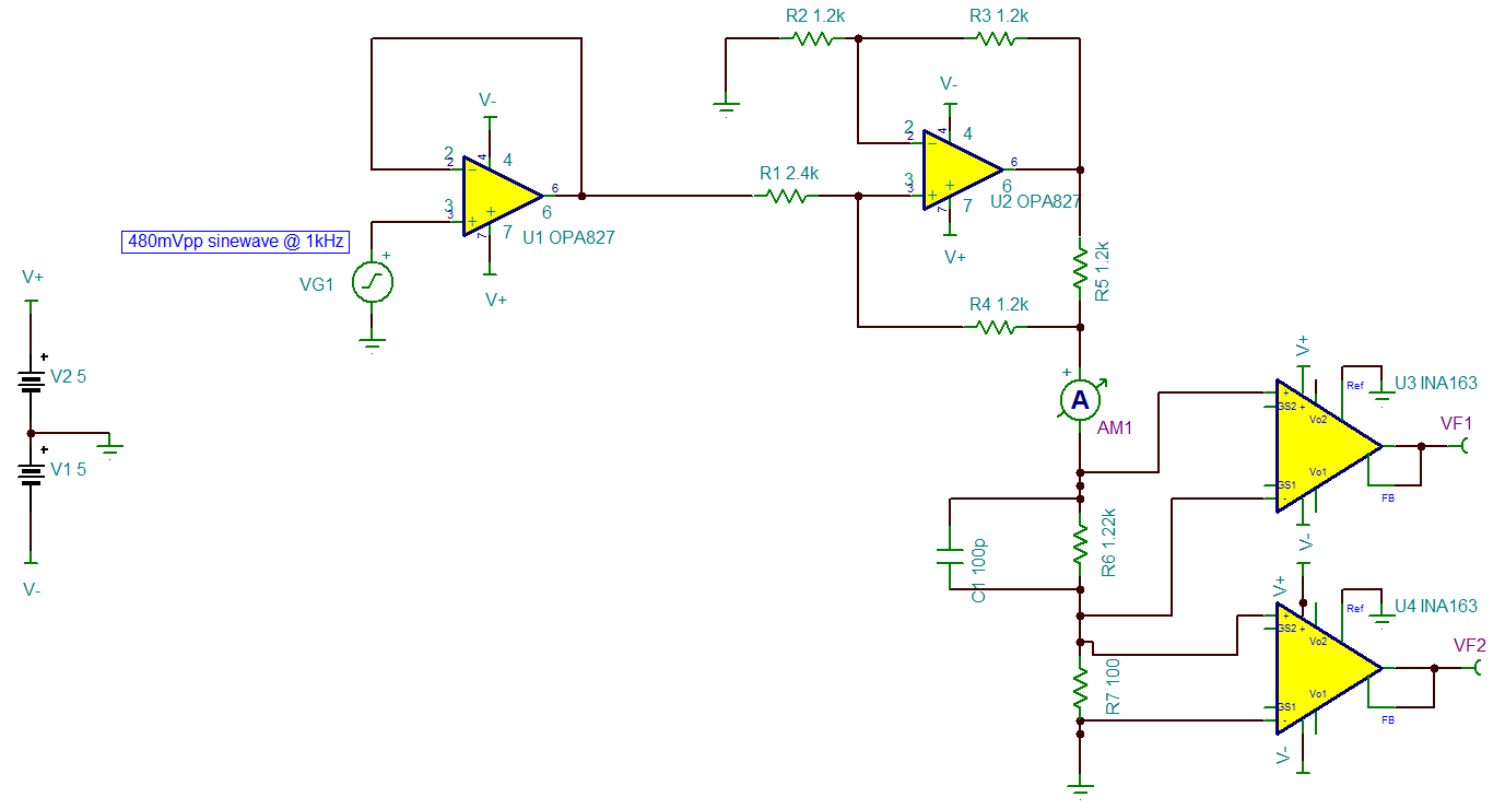
I am implementing the following schematic:
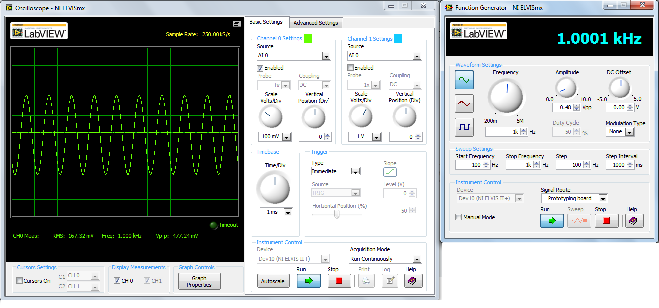
The input waveform VG1 is obtained as:
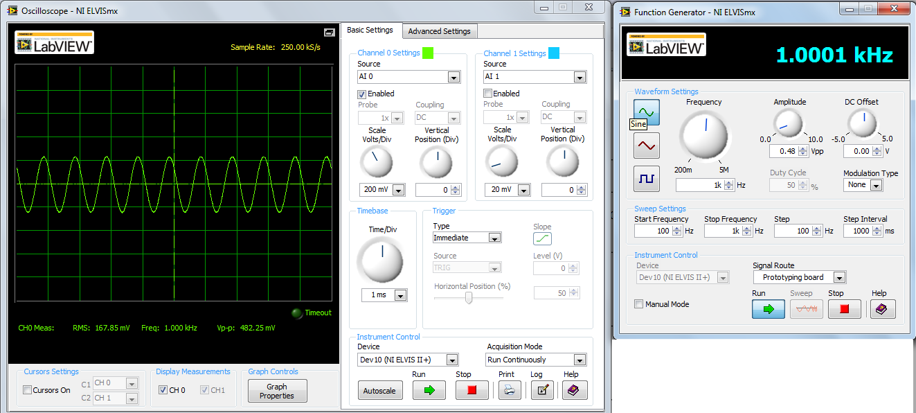
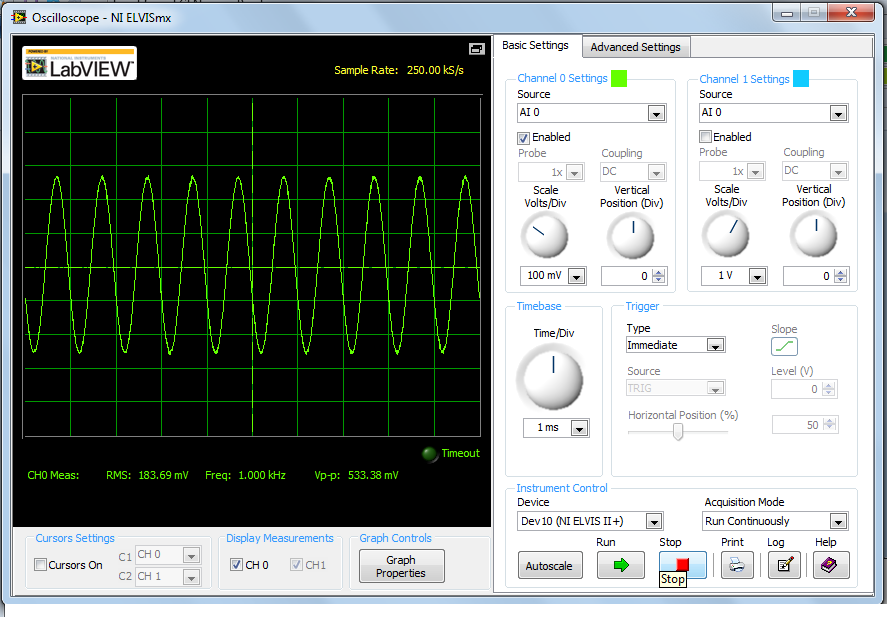
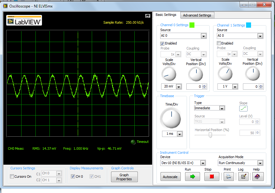
The output waveforms as obtained from two INA163 instrumentation amplifiers(VF1 and VF2 in schematic) are shown below:
VF1:
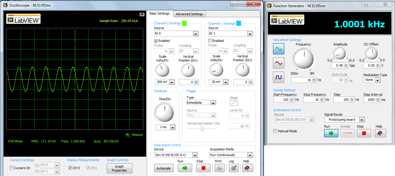
VF2:
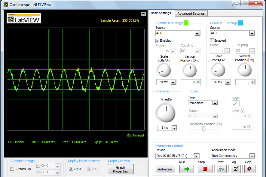
The waveform VF2 appers to have some noise.When a 480mVpp sine was directly given as input to U4(INA163),the output obtained was:

Is there any way of correcting this?