This thread has been locked.

If you have a related question, please click the "Ask a related question" button in the top right corner. The newly created question will be automatically linked to this question.

Current limited for xtr105

Other Parts Discussed in Thread: XTR105

Hi, I use xtr105 to designed 4-20 mA transmitter. In a datasheet xtr105 have a current limited at 27 mA but I need to limited at 22 mA. So please advise me. Thank you.

  • Hello,

    The typical over-scale limit for the XTR105 is 27mA, with a maximum value of 30mA.  A 22mA current limit is a strange requirement for a 4-20mA transmitter.  Can you provide a little information regarding why this is required? 

    Since there isn't a way to change the internally programmed current limit of the XTR105, an external current limiting circuit is required.  The challenge with a 22mA current limit is that over the transmitter operating temperature and component tolerances it's going to be very difficult to prevent the current limit from affecting the accuracy of the design at the 20mA full-scale level. 

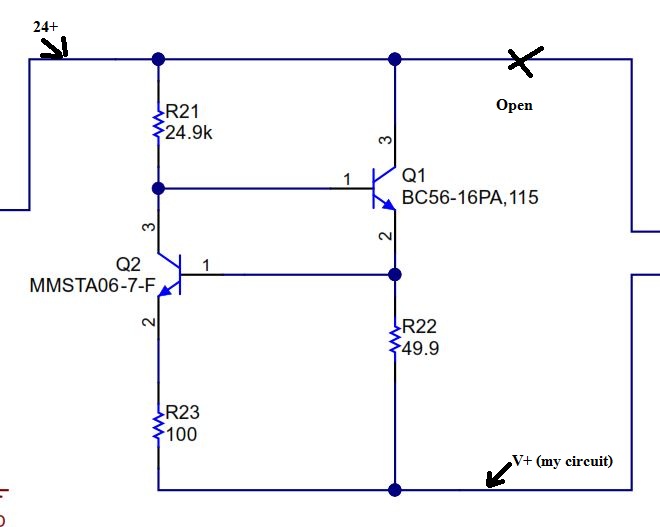
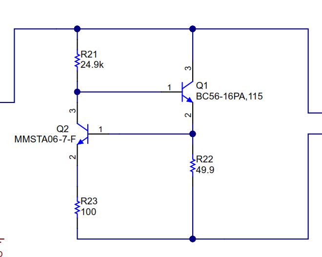
    The most common external current limit is the circuit shown in the image below.  While this particular example wasn't for a 2-wire transmitter, you would connect the loop supply to the top connection and the current limited output to the bottom.  In normal operation the Q1 transistor is biased by R21 and is active allowing current to flow from the loop-supply to the transmitter through Q1 and R22.  When the voltage drop across R22 is high enough (~0.6V) the Q2 transistor becomes active and steals the base current from Q1, limiting the current that can flow through Q1.  Therefore the current limit is set using the equation below:

    I_limit = Q2_Vbe / R22.  So in this example the current limit is roughly 0.6V/49.9Ohms = 12mA. 

    As mentioned above the trouble with this type of circuit is that the Vbe voltage will vary from BJT to BJT and the Vbe voltage changes over temperature at roughly -2.2mV/C.  The R22 resistor will also have a tolerance and will also change value over temperature based on its temperature coefficient.  Therefore this circuit is typically used to set a current limit between 27 - 30mA which prevents it from becoming active and affecting the accuracy at the 20mA full-scale output level.

  • Hi Collin Wells

    I use xtr105 for designed PT100 RTD as picture below. A signal 4-20mA is read by PLC. But analog card of PLC can not endure at 27 mA. So i need to prevent this by limit a signal is not more than 22 mA. Please advise. Thank you.

  • Could you also send us the product number of data manual for the PLC card you're using? It will help us understand where the 22mA requirement is coming from.

    For now, try the circuit I showed in the previous post. You can put it between the +24V supply and the V+ pin of the XTR105 and collector of Q1, or between the output terminal of the XTR105 and the PLC analog input card.
  • Information form my customer , They use ABB PLC, AI801 Analog Input Module ,0(4)..20mA . From your advise circuit ,I could be put it as picture. below 

    Please advise, Thank so much.

  • Hello,

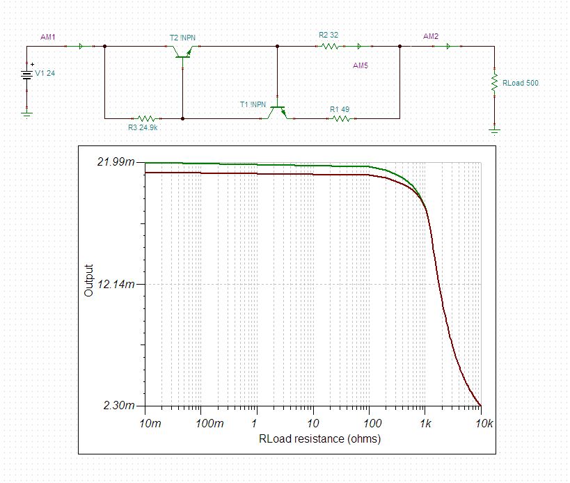
    Yes, you're correct.  Attached is a TINA schematic that you can use to test the behavior of the circuit.  I configured it for a 22mA current limit.  I'd like to state again that setting the current limit 2mA away from the 20mA full-scale level will likely introduce errors over temperature and product variation as the current limit will affect the 20mA output levels.

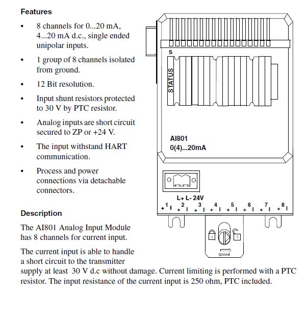
    Also, while I trust the customer knows what they are doing I looked at the product manual for the AI801 from ABB and it states that the PLC module has an internal current limit.  See image below:

    Here's an image of the circuit and results.  Notice that as the load current continues to decrease the output current is limited to 22mA.  Also notice that the knee of the curve includes 20mA which is why I mentioned that such a low current limit will likely affect the 20mA output level.  The TINA file is attached below it so you and the customer can test the circuit operation.

    Simplified_Current_Limit.TSC

  • Ok , it clearly. Thank you so much