This thread has been locked.

If you have a related question, please click the "Ask a related question" button in the top right corner. The newly created question will be automatically linked to this question.

Problems on modeling THS4303 in ADS

Other Parts Discussed in Thread: THS4303, THS4304, TINA-TI, LMH6703

Hi, everyone, 

I want to simulate a positive feedback circuit with THS 4303 using S-parameter simulator. There is model on the website, which can be used in ADS.

However, I find the real port of the input impedance of the feedback circuit is about 20-40 Ohm, which is not accordance to the experience, because the feedback circuit only contains reactance components.

So, my question is, is the ADS model provided on the website is OK for my simulation ? or I can use the op amp model in ADS with its parameters filled according to the datasheet ? 

  • Jason,

    Can you provide a little more detail on your circuit and the goals of your simulations?

    At this time we don't have enough information to answer your questions.

    1. Can you upload your circuit schematic to this thread?
    2. What metrics will you be looking at in your simulations?
    3. What is the expected outcome?
    4. How does the model & ADS circuit differ from what you expect?

    Any additional information would be helpful.

    Regards,
    John

  • Dear John,

    Sorry for late reply.

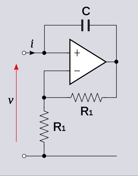
    I want to realize the negative impedance using the following circuit

    However, I find real part of the realized input impedance is not zero, and it is a frequency-dependent parameter. So is the imaginary part, which is the negative capacitance that I want to get.
    So, is the model suitable for this circuit ?
  • Jason,

    The THS4303 has been optimized to use the existing internal resistor values of Rg = 50 ohms, and Rf = 450 ohms.
    Your schematic shows equal resistances for the feedback path.
    Is this what you are trying to simulate?

    Regards,
    John

  • Dear John,
    Yes, I'm trying to simulate this circuit. Do you think its OK to add a resistor of 400 Ohm between the inverting port and ground?

    I also find that, the performance of the circuit is sensitive to the bias circuit. For example, there is a big difference between the following two cases : case 1, without RF-block inductance; case 2, with RF-block inductance. So, is that the truth ? Should I simulate the circuit with the bias circuit ?
    Regards,
    Jason
  • Dear John,
    I have one more question, is there a op amp product that have the same core as THS4303 but without the internal Rg and Rf ? Maybe it is more attractive to me ..
    Regards
    Jason
  • Jason,

    It is hard to recommend a device without knowing the design goals for the circuit.
    That being said, the THS4303 is closely related to another device, the THS4304 that has no internal gain-setting resistors.
    Perhaps the specs for the THS4304 will meet your goals.

    Fortunately we have product experts who can help pick the best device for your application, and can also help with your circuit-design questions.
    They are the applications engineers in the product line and they monitor the High Speed Amplifier E2E forum.

    I will move your inquiry to that forum.

    Once the product engineers have answered your design-related questions, they can move the discussion thread back to this forum to take care of any remaining model or simulation questions.

    Thanks for your patience and your interest in TI products.
    Regards,
    John

  • Hi Jason,

    I am posting to this thread so that I will get a notification when you add the design criteria.

    I am not familiar with ADS.  I use TINA-TI when I simulate application circuits.  

    To answer your question about using 400 Ohm external resistance for the THS4303:  It appears to me that this amplifier is not unity gain stable.  Adding extra gain set resistance will make the amplifier unstable.  Positive feedback will make this worse.  

    For a unity gain circuit you may want to consider a current feedback amplifier like the LMH6703.  With a current feedback amplifier you can increase stability by using a larger feedback resistor. 

    I would recommend against using S parameter simulations for this application.  S parameters are only fixed for a given signal amplitude (and steady state conditions) while amplifier response will change with signal amplitude and bias conditions.  This will be particularly important in this application with the positive feedback.  I would recommend using transient simulations to test this circuit, not S parameter based simulations.

    A circuit simulation model is only an approximation of real circuit behavior.  A positive feedback circuit is a very demanding condition to model.  With a current feedback amplifier you will have the extra freedom of the feedback resistor value to help tweek circuit behavior. 

    Regards,


    Loren


  • Dear John,
    Thank you for your help !
    Regards
    Jason
  • Dear Loren,

    Thank you for your reply !

    My goal is to design a negative inductor from 0.1-0.5  GHz, using an op amp chip.

    The topology is shown as follows:

    from : en.wikipedia.org/.../Negative_impedance_converter

    And the input impedance of the circuit is Z=-R3*R1/R2.

    I think it could replace R3 by an inductor, and an negative inductor could be realized.

    This is a grounded NIC circuit. And furthermore, I want to design a floating NIC, whose topology is shown as follows:

    And do you think THS4303 is OK? or  LMH6703 is better ?

    Thank you !

    Regards !

    Jason


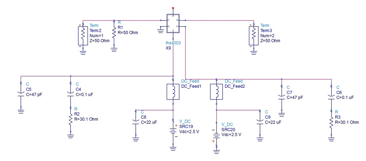
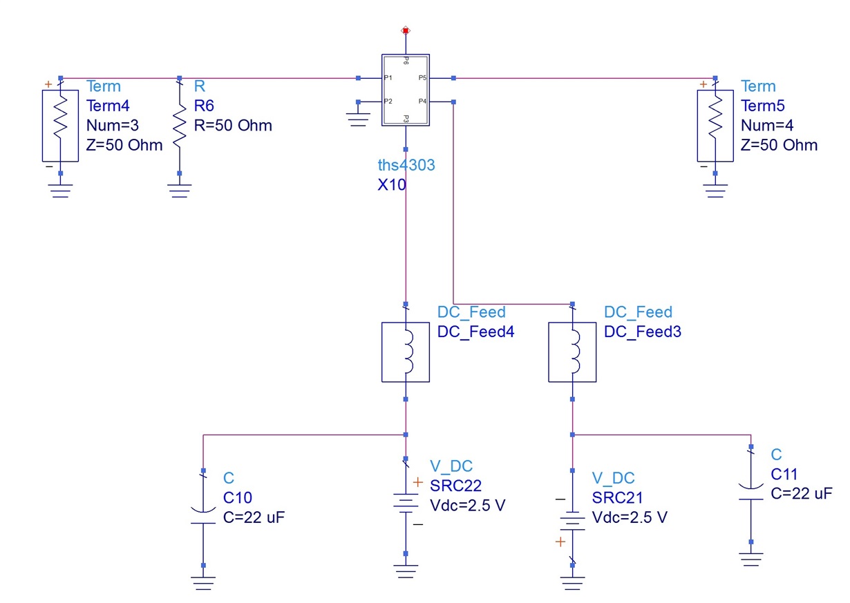
  • I made a comparison between the following two circuit, one is with the decoupling circuit in the bias network and the other one is without the decoupling circuit.

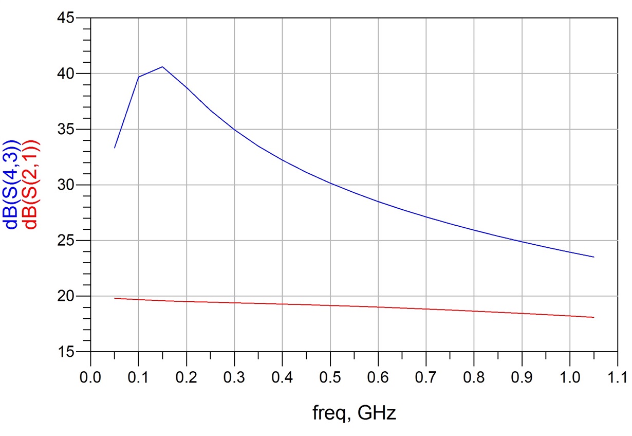
    I found there is a big difference between the two results.


    So I have two questions :

    1. Does the THS4303's ADS model could take the bias state into account ? (Does the dB(4,3) is reasonable)?

    2. Is the decoupling circuit necessary for the circuit? (the capacitance as well as the resistor is used for providing the AC loop ?)

    Thank you !

    Regards !

    Jason 

  • Jason,

    The THS4303 ADS model does depend on the bias state of the circuit.

    Also, the model is intended to work with low impedance power supply circuits.

    I suspect you are seeing differences because the DC Feed acts as a high impedance for higher frequencies.
    The extra caps in the first circuit provide AC shorts to ground at the power supply pins. So the dB(2,1) curve is what we would expect.
    The second circuit only has the DC feeds connected to the supply pins and these act as high impedances. This is what causes the dB(4,3) curve to look strange.

    My suggestion is to remove the DC feeds and supply the model directly from the DC voltage sources.

    Regards,
    John