This thread has been locked.

If you have a related question, please click the "Ask a related question" button in the top right corner. The newly created question will be automatically linked to this question.

Single ended to differential conversion for ads1278

Other Parts Discussed in Thread: ADS1278, THS4521, OPA4192, OPA192

Hello engineers,

I have a single ended signal that i want to convert to be differential so that i can use the full scale of the differential ADC (ADS1278).


The single ended signal that i want to use is 0V-2.5V. The ADC input range goes from +Vref to -Vref, i have the Vrefp tied to 2.5V and the Vrefn tied to ground. To convert the signal a THS4521 differential amplifier is used.


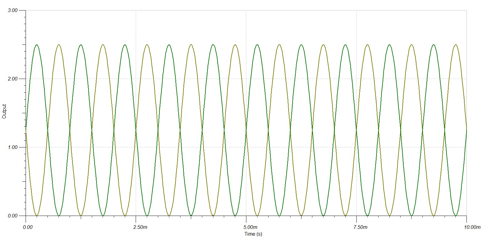
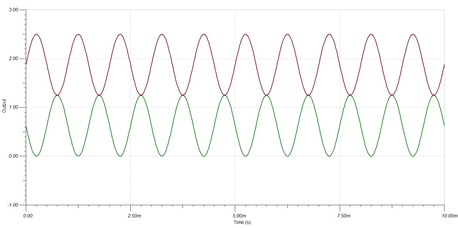
Now from what i know, when the single ended signal looks like this:

The differential signal should look like this:

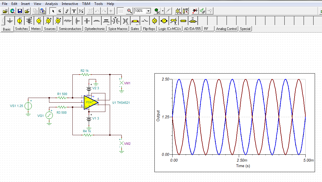
But when i use the single ended to differential schematic from the amplifiers datasheet, i get the following signal:

(Vocm is set to 1.25V)

Now i can see that the pk-pk voltage of this resulting differential signal is the same as the single ended signal (2.5V). But is is different from what i thought that was going to happen (image 2). Can anyone explain to me why this happens or what i am not understanding about differential signals?


Thank you,

Fransisco

  • Hi Francisco,

    The THS4521 is a High-Speed Amplifiers and there is a separate E2E forum for those amplifiers. Nonetheless, I took a stab at solving your circuit issue with the single-ended input, differential output circuit. 

    The dc level accompanying the ac generator signal causes the two outputs to have different dc levels and that is why they do not overlay. That same common-mode voltage, 1.25 V in this case, must be applied to the other input as well. That will force them to overlay, but then that common-mode voltage is rejected by the amplifier and the two outputs will overlay on 0-volts. To move the outputs off of 0-volts, the Vocm output common-mode function must be employed. That is where 1.25 V is applied to shift the output upwards by that level. The same 1.25 V source can be used for both the inverting input and Vocm input.

    Then, the gain of the circuit is half of what it needs to be to achieve 2.5 Vp-p at each output. The full gain is seen across the two outputs, but each individual output sees only half the output to ground. Therefore, the gain must be increased to 2x.

    When you do each of the things I've described the output becomes what you are after. You can see the results below.

    Do note that the THS4521 is only usable with supplies to 5.5 V total. Therefore, the +/-3 V I used in my simulation was done to illustrate how to go about accomplishing what you needed. In practice, the THS4521 would use +/-2.5 V supplies and then would not be able to swing to +2.5 V at the output. The output will clip before that level is reached due to output swing limitations. Keep this in mind when you are designing your circuit. 

    If you need anymore assistance with this application, please address your questions about the THS4521 to the High Speed Amplifiers E2E forum.

    Regards, Thomas

    PA - Linear Applications Engineering

  • Hello Thomas,

    Thanks so much for the very complete answer! I have the simulation working and understand how to get the signals the way I want them to be.

    Greetings,
    Fransisco
  • I have to convert single ended to differential output.

    Single ended voltage is 0 to 5 volt
    and i need differential output from +10 volt to -10 volt.

    Like,
    For 0 Volt : Requires -10 volt
    For 0.5 Volt : Requires -8 volt
    For 1 Volt : Requires -6 volt
    For 1.5 Volt : Requires -4 volt
    For 2 Volt : Requires -2 volt
    For 2.5 Volt : Requires 0 volt
    For 3 Volt : Requires +2 volt
    For 3.5 Volt : Requires +4 volt
    For 4 Volt : Requires +6 volt
    For 4.5 Volt : Requires +8 volt
    For 5 Volt : Requires +10 volt

    Is there any IC is available in TI then please suggest me.
  • Hello Kiran,

    Please see the circuit below. A 0 to +5 V input is converted to a differential -10 V to +10 V output configuation. Since three OPA192 op amps are required, the OPA4192 quad op amp may be the best option. Some additonal circuit development would be required to optimize the interface between this driver circuit and the ADS1278.

    Regards, Thomas

    Precision Amplifiers Applications Engineering