This thread has been locked.

If you have a related question, please click the "Ask a related question" button in the top right corner. The newly created question will be automatically linked to this question.

Value Of Isolation Resistor For OPA4317

Other Parts Discussed in Thread: OPA4317, OPA317, TINA-TI

Hi,

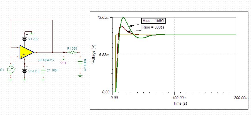
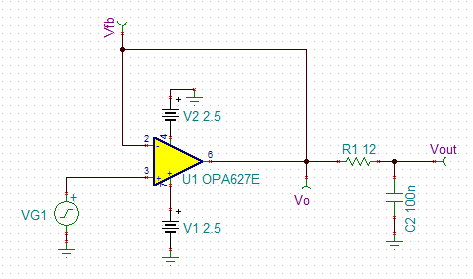
In a design I am using OPA4317 as unity gain buffer. I am using single supply 3.3V. I want to drive 0.1uF capacitor with it, what should be the value of isolation resistor so that this design doesn't face instability. Does it depend on signal frequency.


Thanks,
Prashant Tripathi

  • Hello Prashant,

    You can simulate the stability of the OPA317 driving a 0.1uF capacitor using the free SPICE simulator TINA-TI.  For more information on the stability analysis techniques used for these results, watch the TI Precision Labs Videos on Op Amp Stability: 

    We recommend using somewhere between a 150 and 330 Ohm resistor depending on the type of response you're looking for.  See below:

    1205.Circuit.TSC

  • what happens when you put the series resistor inside the loop? Timothy Darling
  • Hi Timothy,

    As per my understanding if you put resistor inside the loop as shown in below circuit then it will be in series with your op-amp's output impedance Z0. So instead of helping you this will degrade your circuit's stability.

  • Hello Timothy,

    Prashant is correct.  Placing the resistor inside the loop will increase the effective open-loop output impedance which will make any issues caused by capacitive loads worse.  Using the "Riso+Dual Feedback" circuit uses a capacitor between the output and inverting input to make the circuit look like the "Riso" circuit at high frequencies.

    This is all covered in the TI Precision Labs Videos on Op Amp Stability: 

  • Hi Prashant,

    The OPA4317 is a low offset chopper amplifier and is most suitable for DC applications. To drive a capacitive load, a better solution would be to use an OPA627 or OPA625. You could use a much smaller isolation resistor in this case as well. Please see the simulation results below:

    Schematic:

    Loop gain and Phase Margin analysis:

    Results:

    As seen, the Phase Margin is well above 45 degrees.

    Transient response:

    Transient response using a 50kHz square wave on the input.

    As seen, the results are very stable and there is only a slight overshoot.

    Please let me know if you have any questions.

    Regards,

    -Eric Beljaars

    OPA627.TSCOPA627LoopGain.TSC