This thread has been locked.

If you have a related question, please click the "Ask a related question" button in the top right corner. The newly created question will be automatically linked to this question.

INA2331 inaccurate gain?

Other Parts Discussed in Thread: INA2331, INA331

Hi, 

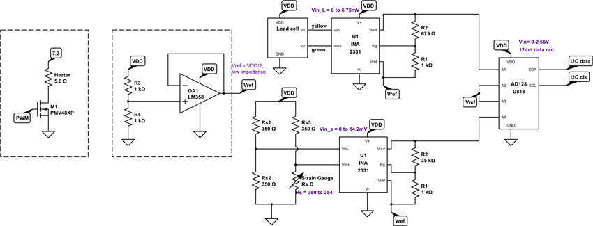
 I am using an INA2331 as a differential amplifier for a single varying resistor bridge. I am using it with single supply of 3.3V, therefore, I have an external reference of about 1.65V. The expected output of the bridge is up to 14mV, and the gain used is of 110 using R2=21k, R1=1k, and the shutdown pin is connected to V+

The circuit I am using is as the one depicted in Figure2 of the datasheet. 

However, with an input of 4mV, the output I measure at the output is even below the reference, and therefore get a negative value. 

Is there more calculations needed to set a correct reference voltage? My input is DC so I am not sure how to apply the input common mode calculations in the datasheet. Can someone see what I am doing wrong?

  • Hello Nathaly,

    Please measure the voltage at pins 2, 3, and 12 of the device (Vin-, Vin+, and REFA). It is of utmost importance to measure at the pins of the device...not anywhere else (e.g. test points). We need to ensure that the device is receiving the voltages we think it is.

    On a side note, please understand that the 'A' version of the INA2331 has a maximum offset voltage of 1mV, which is 25% of your input signal. Also, please ensure that your reference is driven by a low impedance source (e.g. op amp buffer). It should not be driven by a resistor divider. Also, please ensure proper power supply decoupling on the PCB as discussed on page 9 of the data sheet. Finally, I assume you're using precision resistors (0.1% or better) for R1 and R2. If not, you should measure them and calculate your actual gain. Once you have the measurements, please calculate the expected output voltage and compare it to the measured output. As mentioned before, the offset voltage of the 'A' version is up to +/-1mV, which equates to +/-110mV at the output (assuming G=110V/V). The 'non-A' version, however, may have up to +/-55mV at the output due to the offset voltage.
  • Hi Pete, thanks for your reply.
    I do have Vref coming from an opamp buffer. I added the decoupling capacitor I was missing but it didn't seem to change much.


    My input is coming from a wheatstone bridge with only one resistor changing, At balanced, all Resistors in bridge are 330ohms. I measured the input and output (reffered to Vref) directly at the pins and I've attached  the results. The theoretical gain is calculated using the gain eq G=5+(5*R2/R1), where R2=21200, R1=1000. The difference between the expected (named Theo in my table) and the measured values is not linear, so I am not sure the offset is to blame.

    vs vref R bridge s Vin meas vout meas gain meas gain theo vout theo vout diff
    3.297 1.647 330 0.142 -1.02 -7.183098592 140.8974359 20.0074359 21.0274359
    3.297 1.647 331.1 2.77 11.87 4.285198556 140.8974359 390.2858974 378.4158974
    3.297 1.647 332.4 4.936 23.16 4.692058347 140.8974359 695.4697436 672.3097436
    3.297 1.647 333.6 7.75 36.97 4.770322581 140.8974359 1091.955128 1054.985128
    3.297 1.647 334.8 10.28 49.65 4.829766537 140.8974359 1448.425641 1398.775641
    3.297 1.647 336 13.73 66.7 4.857975237 140.8974359 1934.521795 1867.821795
    3.297 1.647 337.1 16.22 79.15 4.879778052 140.8974359 2285.35641 2206.20641

    I have attached a schematic, albeit with a different Resistor values, if it helps at all. 

    This test was done in a breadboard, although in a PCB I got similar results I just couldn't control the input. I will try the same test with a new chip to see if I get consistent results, but otherwise, I am not sure why I am not getting the expected gain!

    Thanks

  • Hello Nathaly,

    I assume the 'Vin meas' and 'vout meas' columns are in mV, right?

    I'm a little confused by the gain. In the table it is listed as ~140.9V/V. However, given R2=21.2k and R1=1k, the gain should be ~111V/V.

    My next recommendation is to completely isolate the INA331 from the system by disconnecting the inputs and outputs. Then provide it with a known input voltage (make sure the common-mode is still near mid supply). Also, as you suggested, try a new device. These results are very odd. Finally, I should add that the gain of every device is tested before it is shipped to the end customer.