This thread has been locked.

If you have a related question, please click the "Ask a related question" button in the top right corner. The newly created question will be automatically linked to this question.

INA332 Gain Problem

Other Parts Discussed in Thread: INA332, INA331, OPA320, INA326

Hello,

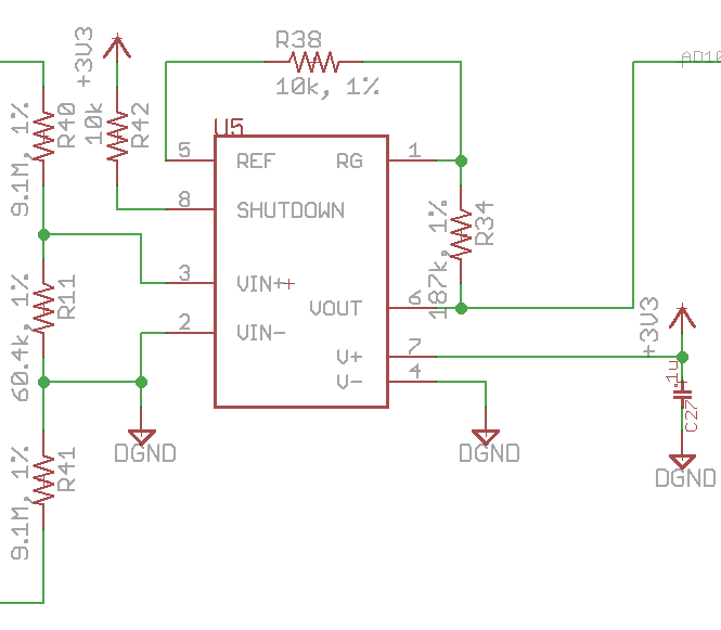
I am trying to use a INA332, and I am going to try to attach a schematic of how I have configured it.  It is currently on a breadboard, and I am changing the 2 gain resistors on the INA332 to try to get a circuit consistent with the documentation.

Currently, the problem is that my data shows a Gain function of Vo = Vi * (5 + .75 * R2/R1)    {R2,R1 = R34,R38 in my schematic}  The datasheet says the gain should be 5 + 5 (R2/R1) ... Note the coefficient before R2/R1 is 5 in the datasheet, but .75 in my results.


After getting this result the first time, I tried to also use a unity gain buffer using an op amp, but I still see the same results = .75 coefficient.

Has anybody seen the 5+5(R2/R1) work?  Why might my circuit have a different gain?  Any ideas?

Thank you!

R2(kohm) R1(kohm) Vin INA332 (mV) Vout (mV) Gain Coefficient
0 open 168 803 4.779761905  
10 10 168 922 5.488095238 0.708333333
20 10 168 1050 6.25 0.735119048
30 10 168 1170 6.964285714 0.728174603
40 10 168 1300 7.738095238 0.739583333
50 10 168 1430 8.511904762 0.746428571
60 10 168 1570 9.345238095 0.760912698
70 10 168 1690 10.05952381 0.754251701
80 10 168 1820 10.83333333 0.756696429
90 10 168 1940 11.54761905 0.751984127
100 10 168 2060 12.26190476 0.748214286

  • Hello Matt,

    The INA331 is operating on the edge of linearity when used in low-side current sensing (please see common-mode input range vs reference voltage plot on page 5 of the data sheet).

    Given that this is a low-side measurement and that no reference voltage is present, I recommend using an op amp for this application. Perhaps you could evaluate the OPA320 because it is a RRI/O device, operates on a 3.3V supply, and has a shutdown pin.

  • Hello Matt,

    I just noticed that there is no reference voltage connected to pin 5.
  • Hey, Pete,

    I am definitely open to other chips.  Unfortunately, an opamp won't do it.  The problem is that I am trying to sense a difference between Neutral and earth GND (input side) and outputing a signal on the output side that is referenced to the digital ground so my micro can read it.  That digital ground may be any arbitrary potential with reference to the earth ground.  (Note that in the schematic I posted, the Vin- of the chip shows a connection to DGND, but this was only a temporary hack to make this chip work, and that connection to DGND should not exist)

    I have been looking at isolation amplifiers, but all I see require approximately 5V input side supply.  I have 120VAC and 3.3VDC.  That's it.  :(  The idea with an isolation amplifier was going to be to use a DC-DC converter to make another 3.3V isolated rail that would reference earth ground on one side and supply the input side of the isolation amplifier.

    Any ideas to make this work?


    Thanks,

    Matt

  • Hello Matt,

    Thanks for the additional information. Now that I understand more about your application, I suggest trying the INA326. It is the only true RRI/O instrumentation that we have in our portfolio. With a single 3.3V supply the input common-mode range is -20mV to 3.4V. The output swing depends on load, but let's say it's typically 10mV from either supply rail (e.g. 10mV<Vout<3.29V). You should ensure that the product of the INA326's gain and the difference between the ground potentials that you're trying to measure is greater than 10mV (though you may want to add margin and make this 75-100mV). Note two additional things about using the INA326. First, it is meant for dc precision and therefore has limited bandwidth. Second, the gain setting pins of the device are very sensitive to parasitic capacitances, so be sure to layout the PCB carefully.

    One concern I have to mention is the grounding scheme. I recommend creating/using a quiet analog ground for the INA326. This is because a noisy digital ground will not only add dc error via PSRR, the input common-mode range is determined by the supply voltages. Here are a couple references that may be of help:

    www.ti.com/.../sloa089.pdf

    e2e.ti.com/.../sar-adc-pcb-layout-the-reference-path