This thread has been locked.

If you have a related question, please click the "Ask a related question" button in the top right corner. The newly created question will be automatically linked to this question.

Designing 4 to 20mA transmitter for thermocouple using xtr112

Other Parts Discussed in Thread: XTR112, XTR101

Hi, have some experance by designing thermocouple using the xtr112? 

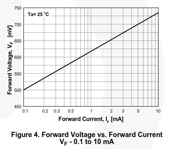
recently I am confused by the CJC(cold junction compensation), according to the datasheet I should use a diode(LL4148), a 1k Ohm and a 25  Ohm resistor to compensate the cold junction, but according to my measurement the cold junction was far not enough compensated. So I measured the forward voltage over the diode, there was only about 0.2V, according to the datesheet of LL4148 the forward current through the diode was about  only 1uA.

According to the datasheet xtr101 these two resistors are 2k Ohm and 51 Ohm, but in compare of the xtr112 the xtr101 has a much greater current stimulation(1mA), does it means the 1k Ohm and the 25 Ohm also needs to be changed to resistors with much greater values so that the voltage over the diode can reach 0.6V?

right now I am confused by this CJC problem, can anyone help me?    

  • Hello,

    Diode based cold-junction compensation is based on scaling the change in forward voltage of a diode ~ -2.2mV/C to match the average Seebeck coefficient of the thermocouple type that you're using.  

    As shown in the image from the LL4148 datasheet, with the 250uA excitation currents of the XTR112, the LL4148 forward voltage should be roughly 540mV.  Since you're measuring a forward voltage of only 0.2V I suggest you double-check the circuit connections.  You could also test the diode using a current source and voltage meter to see if the diode is behaving as it's specified in the datasheet.  If it's not I suggest obtaining a different diode from another manufacturer.

    Assuming you're trying to match a 52uV/C Seebeck coefficient, you can size the voltage divider as shown:

    52uV/C = 2200uV/C * ( R1/ (R1+R2)).  Where R1 is the bottom resistor of the resistor divider and R2 is the top resistor. 

    Depending on the diode you can vary the diode change in forward voltage from between -2000uV/C to -2200uV /C to tune the system.

  • Hello Collin,

    thanks for the reply, the resistance of the diode by 250uA should be about 540mV/0.25mA=2200Ohm, and the  resistors for the scaling are 1k and 25Ohm, which is much smaller than the resistance of the diode, which means the scaling resistors are bypassing most of the current, so it is impossible that the whole 0.25mA flows through the diode. Am I thinking correct?

  • Yes, you're correct that's likely the issue as I didn't notice how low the values were in the XTR112 datasheet. Try seeding the R2 resistor in the equation provided in the previous post with 49k and most of the current will be diverted through the diode.
  • thanks Collin, I tried the R2=49K R1=1.5K and instead of the 50Ohm trimmer a larger Value trimmer, now it is working!
  • Nice work!  Next time we get into the datasheet we'll update the circuit diagram.

    Thanks for your feedback!