This thread has been locked.

If you have a related question, please click the "Ask a related question" button in the top right corner. The newly created question will be automatically linked to this question.

XTR117 Problem with functionality

Other Parts Discussed in Thread: XTR117, RCV420, ISO122, XTR105

Hello,

I am using XTR117 device trying to implement the circuit described in Figure 9 of the RCV420 datasheet (the following one). 

The part of the RCV420 and ISO122 is exactly THE SAME as the above design. But instead of the XTR105 device, I´m using the XTR117. 

For that part, I am using the following schematic : 

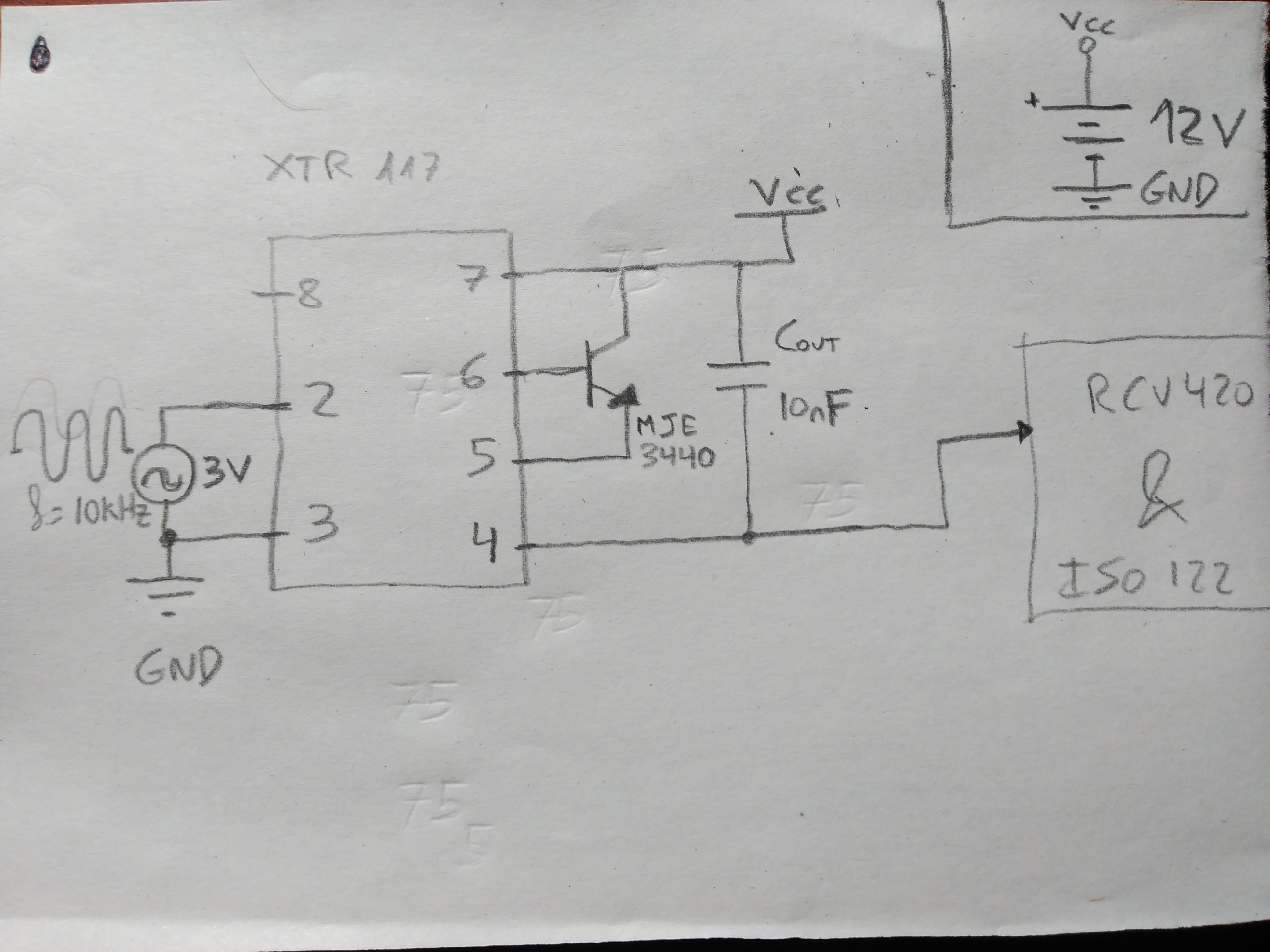
The signal input is a sinusoidal wave of 10 kHz. The pin 7 is connected to power supply: 12 VDC, (not the +15VDC from the RCV420 & ISO122 circuitry) and pin 3 (IRET) is connected to the same GND reference as the sinusoidal and power supply signals.

The results of this is that the input signal is deformed considerably at the entry of the circuit. And the pin 4 (IO) does not give any signal.

The transistor receives square pulses in pin 6 and pin 5 similar to this situation.

- Is the Iret connection to GND reference the mistake? Or is the loop supply the problem or the transistor?

- Is the 1N4148 really important for the operation of the circuit or can it be removed?

- Could you please help me to solve this problem?

Thank you very much,

  • Hello,

    This looks like a common grounding issue that occurs in 2-wire transmitters.  I covered this issue in great detail in part 2 of a 6 part blog series I wrote on designing with 2-wire 4-20mA transmitters:  Part 2

    In short, you can't connect the IRET pin of the XTR117 to the same GND that the receiver and +12V supply are derived from because the transmitter has to float up and down in relation to the loop GND (RTN) as the output current changes.  This can be an issue when trying to test these circuit in the lab because most lab instruments feature an "Earth Ground" referenced output which prevents them from floating with respect to each other.  Try configuring a potentiometer as a voltage divider, with the two ends connected to VREG and IRET and the wiper connected to the Iin pin.  This will work as a floating input source to test the basic operation of the circuit if you don't have any floating voltage sources in your lab.

  • Hello again,
    First of all, thank you Collin for your quick response.
    I´ve read Part 2 of your blog and now I understand why I do NOT have to connect pin 3 (Iret) to the Loop GND.

    So my question is:
    Where do I connect pin Iret in the schematic, which is in the 1st post, so that the circuit works?

    Thank you very much
  • Just so we're clear, the blog explains why the IRET pin can not EVER be connected to the Loop GND.

    The IRET pin is the "local GND" for the 2-wire sensor circuitry that is powered from the XTR VREG output. So in your original figure the IRET pin needs to connect to the GND/reference of the input voltage generator. However, the GND/reference for your voltage generator can not be referenced to a potential with a hard reference to the loop-supply.