This thread has been locked.

If you have a related question, please click the "Ask a related question" button in the top right corner. The newly created question will be automatically linked to this question.

LPV521 gain

Other Parts Discussed in Thread: LPV521, LPV542

Hi there, 

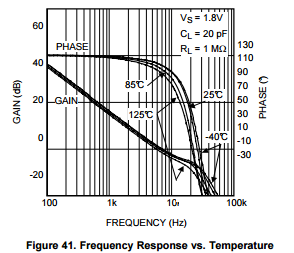
I am considering using the LPV521 in op amp in a band-pass amplifier/filter design. The amplifier will have a low BW (0.1-20Hz). I want to know what is the maximum gain I can achieve at 20Hz using the LPV521. The datasheet seems to only show gain values down to 100hz.

  • Hi Trevor,

    The gain slope is 20dB/decade, until it intersects the "DC" gain at some lower frequency. The "DC" gain will be about 120dB, and the pole will be below 1Hz.

    You can extrapolate back to 20Hz by looking a decade beyond. The gain at 200Hz is about 30dB from the graph, so that would be 30dB + 20dB = 50dB at 20Hz.

    Theoretically, you could have an closed loop gain of up to 50dB, but you *really* want to have at least a minimum of 20dB of open loop gain left at your highest signal frequency. So now we are back to 30dB for a max closed loop gain (30dB = 32 V/V).

    So you probably do not want to go more than a gain of 30V/V.

    Regards,

  • Thanks for your reply Paul.. 

    In my application, I was initially only going to use 1 stage of amplification but I need the 50 db gain @  20hz. so it now looks like I will have to use 2 stages to be safe. I see that the LPV542 is EMI hardened also but I can see no further data on EMIRR in the datasheet. Does the LPV542 have the same EMI characteristics as the LPV521, if not, is that information available? 

    Cheers

    Trevor

  • HI Trevor,

    The LPV542 has EMI hardening similar LPV521, but EMIRR was not characterized at the time. Performance should be similar, but not exactly the same (actual EMI performance is very layout and circuit specific).

    In either case, in order for the EMI filter to function at it's best, the supply pins should have a low impedance AC path directly to ground. This is easily done by adding small value, physically small (0603 or smaller) 33 to 470pF caps, directly from the supply pin to a solid RF ground.

    Regards,

  • Hi Paul,

    Just wondering what are your thoughts on directly connecting a capacitor (e.g. 100pF) between the inverting and non-inverting pins on the LPV542 are?

    I have read from some sources that connecting capacitors directly onto the inverting pin of an op-amp may cause instability.. 

    Regards

    Trevor

  • HI Trevor,

    Yes. Adding these capacitors can cause instability - ringing or outright oscillations. Adding a capacitor directly across the inputs can cause peaking at high frequencies, as the cap provides a parallel AC path to the gain setting resistor.

    Because of the high impedance used in micro power circuits, even a "small" (stray) capacitance can make a big difference.

    This issue is covered in great detail in the TI Precision Labs videos on op amp stability.

    The attached presentations, created by Tim Green and Collin Wells, provide techniques for solving voltage feedback op amp stability problems.

    Updated 10/13/2014

    PART 1: 4064.Solving Op Amp Stability 2014_Part 1.pptx

    PART 2: 2514.Solving Op Amp Stability 2014_Part 2.pptx

    PART 3: 8203.Solving Op Amp Stability 2014_Part 3.pptx

    PART 4: 2766.Solving Op Amp Stability 2014_Part 4.pptx

    The effects can easily be simulated. Be sure to use pulsed input signals to observe the stability.

    Regards,

  • Thanks very much for the information Paul.. it's very helpful..