This thread has been locked.

If you have a related question, please click the "Ask a related question" button in the top right corner. The newly created question will be automatically linked to this question.

IR remote controlled home appliances using TLC555CDR IC

Other Parts Discussed in Thread: TLC555

Hi Ti Members

Please find attached image of schematic we used for IR remote controlled home appliances using TLC555CDR IC.

In this we are facing a problem.When we press remote to generate constant output to D flip flop(either 0 or 1) in the pressing time it changes output of D flip flop from 0 to 1 or 1 to 0 many times.

We need a constant output on the 5th pin of D flip-flop.I.e when we press button for 1st time it should give 1 and when we trigger next time it should give 0 at the 5th pin of D flip-flop.

Can you please suggest what we can do to overcome this problem.

  • Hi Jasbeer ,

    I have moved this into clocks and timing forum for support . If you could , please send the scope shots at the output of 555 and output of flip flop along with Vcc and gnd .
  • Hi Ti Members

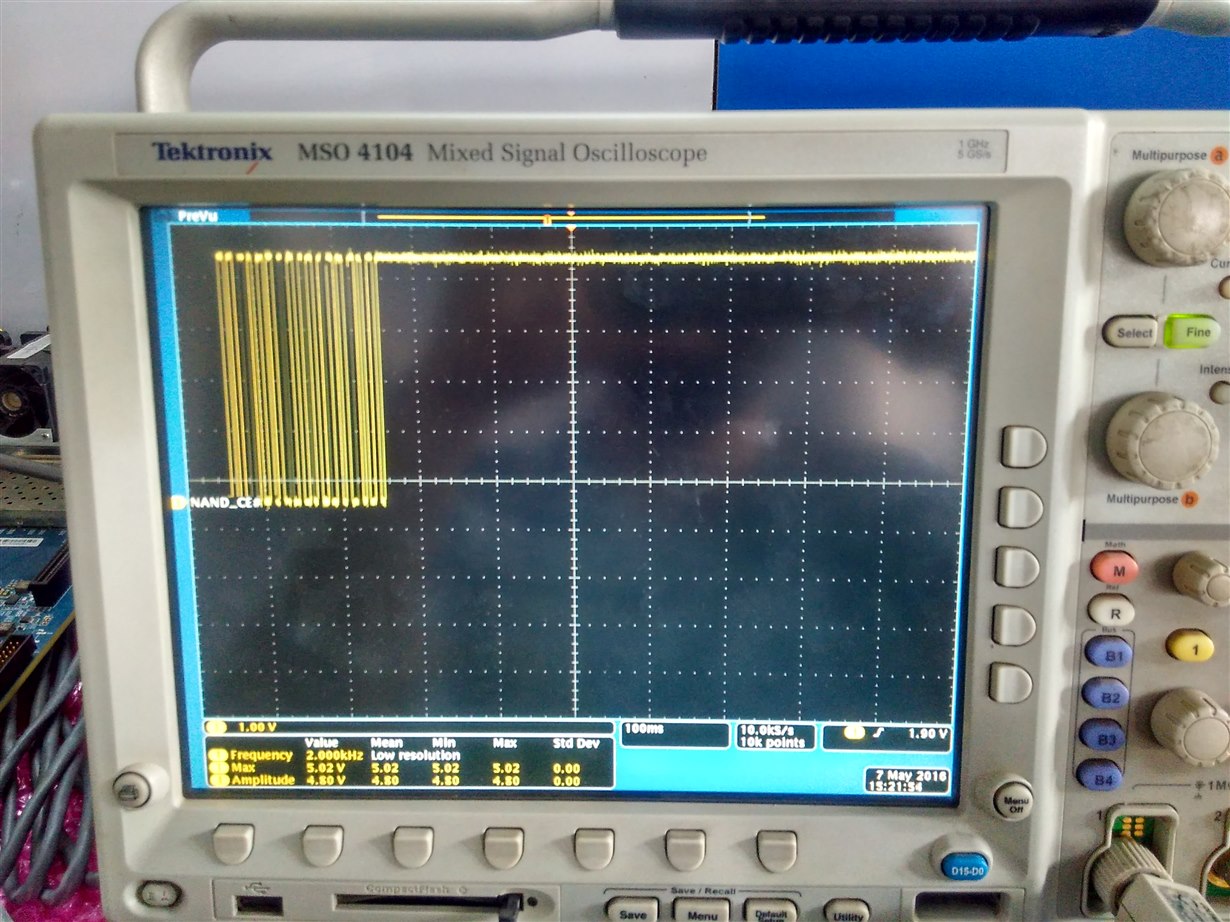
    Screen shot of the output of D flip flop (pin 5) is attached here.
    Please have a look and let me know how to get a constant output either 0 or 1 if gets triggered by remote

      .

  • Hi Ti Members
    I didn't get the reply.
    Please help me ASAP as I got stuck on this point.
  • Jasbeer,

    Precision amplifier is best forum for this timer.

    2nd and final move.


  • Hi Ti Members

    No update till now.
    Can anybody please help me over this question.
  • Jasbeer,

    I sent a notify request to draw attention to this post.
  • Hello Jasbeer ,
    I really apologize for the delay in response

    Can you please send the waveform capture of the output of IC555 ( clock pulse to the flip - flop)

    It will help us a lot in understanding the root of the problem

    Also i was wondering the reason for keeping the pin 5 of IC555 floating ? Please connect a 0.1uF Cap

    capture the waveform at the output of the IC 555(pin 3) , the input trigger pin of the IC555(pin 2) and output of the D flip flop in a single scope capture

    Thank you
  • Hi Jasbeer,

    I suspect the issue you are seeing with the circuit is not due to incorrect 7474, or TLC555, behavior. They just may be responding to the signal coming from the circuit element labeled TSOP. I don't know exactly what it is, but possibly the infrared detector?

    If the IR transmitter controlling the lamp produces switch bounce when pressed, or the TSOP device produces the equivalent of switch bounce, the TLC555 will follow that output signal applied to its trigger pin input. Make sure that the trigger pulse applied to TLC555 pin 2 is clean and doesn't show any evidence chattering when the IR transmitter button is pushed. You can observe that pin using a DSO, but do note adding the scope probe capacitance may change the behavior. If the OUT from TSOP is clean and only produces one output pulse when the IR transmitter button is pressed, then there is something else causing the problem in the circuit.

    An issue I do find with the circuit is that no power supply decoupling capacitors are being used in the circuit. If transients are generated by the TLC555 and 7474 and appear on the supply line everything connected to the 7805 V+ line will be exposed to them. Also, I do believe the 7805 requires an input and an output capacitor.

    Regards, Thomas

    PA - Linear Applications Engineering

  • Yes,Thomas
    you are right.
    This is a TSOP IR receiver .On the output of TSOP we are getting the same fluctuating output.
    Is there any way in the circuit to get a constant output?
    We want to work with this circuit as a switch i.e when i will press any button it should give high output at the D flip-flop.
    Next time when press the remote should get low output to drive any AC appliances.

    Please suggest ASAP.
  • Hello Jasbeer,

    If you do a Google search on "Debouncing the 555 input" and view the Images option, many different ideas are shown. However in your circuit the TSOP is driving the TLC555 trigger input, not an actual push button switch. So the solution may be a little different because the TSOP output may appear a somewhat different than an open-circuit switch.

    One on-line resources has a link via the University of Utah to "A Guide to Debouncing," by Jack G. Ganssle, of The Ganssle Group. I think this guide provides some very sound insight into switch bounce and methods for debouncing them. The sections about hardware and RC debouncers should be most applicable to your application.

    Regards, Thomas

    PA - Linear Applications Engineering