This thread has been locked.

If you have a related question, please click the "Ask a related question" button in the top right corner. The newly created question will be automatically linked to this question.

PGA309 3 wire mode

Other Parts Discussed in Thread: PGA309, PGA309EVM-USB

To whom may it concern,


To operate PGA309A in 3-wire mode, we connect Vout to PRG and ONE to PRG respectively.

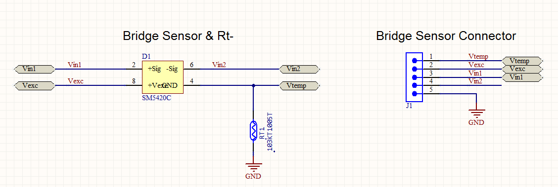
and connect external Rt- (pt100) RTD, as attached picture. I want to calibrate 3-points(-10 / 25 / 80 degrees).

Pls let me know(ppt file for calibration, and pre-cal file), refer to belows.

- PGA309 in 3 wire mode.

- Rt-, pt100 RTD external temperature sensor.

- Vout max and Vout min are 5V and 1V.

- Calibrate Nonlineraty.

3wireMode_RT-_1to5Vout_cal.pdf

- No use Sensor Emulator (use real world sensor).

- use USB DAQ and PGA309EVM-USB program.

Look forward to your reply.


  • Hello,

    Here is the pre-cal file for your desired configuration: 

    HYNUX PGA309 Pre-Cal.txt
    Fullscreen
    1
    2
    3
    4
    5
    6
    7
    8
    9
    10
    11
    12
    13
    14
    15
    16
    17
    18
    19
    20
    21
    22
    23
    24
    25
    26
    27
    28
    [PGA309_Settings]
    Numb Reg=3
    Poly Order=2
    Output Mode=1
    Vout_High_Target=Inf
    Iout_High_Target=0.000000
    Iout_Low_Target=0.000000
    Vout_Low_Target=Inf
    Vs=5.000000
    Vref=4.096000
    Calibrate Nonlin=TRUE
    Reg0=0
    Reg1=0
    Reg2=0
    Reg3=1280
    Reg4=32768
    Reg5=0
    Reg6=5123
    Reg7=0
    Reg8=0
    Temp0=-10.000000
    Temp1=25.000000
    Temp2=80.000000
    Secondary Output Stage=FALSE
    Gain=0.000000
    Offset=0.000000
    Vout_Module_High_Target=5.000000
    Vout_Module_Low_Target=1.000000
    XXXXXXXXXXXXXXXXXXXXXXXXXXXXXXXXXXXXXXXXXXXXXXXXXX

    I recommend checking the PGA309EVM-USB schematic for the necessary connections to the PGA. 

    Best regards,

    Ian Williams
    Linear Applications Engineer
    Precision Analog - Op Amps

  • Thank you answer.

    Still, there is a problem on 3 wire calibration.

    I think there is no problem on schematic of PGA, because i succeeded 4 wire

    mode calibration(not connect Vout and ONE).

    when oscilloscope measuring the ONE wire signal, It is measured differently(3

    wire and 4 wire calibration).

    pls refer to attached picture, and review that should not  3 wire mode

    calibrate(use USB DAQ and PGA309EVM-USB program with received HYNUX PGA309 Pre

    -Cal.txt).  

    Additionally, Please share ppt file for 3-wire voltage output mode.

    -  Rt-, pt100 RTD external temperature sensor.

    -  Vout max and Vout min are 5V and 1V.

    -  Calibrate Nonlineraty.

    - No use Sensor Emulator (use real world sensor).

    waveform.pptx

  • Hello,

    The schematic must be different for 4-wire and 3-wire mode. Please upload your schematic for 3-wire mode so I can determine if there are any issues.

    What information are you looking for in the .ppt file?

    Best regards,

    Ian Williams

  •   6675.Calibration = USB_DAQ + PGA309EVM.pptHello, Ian Williams.

    I upload the 3-wire mode schematic for your review.

    and i also upload .ppt file that including 4 wire mode calibration. it was downloaded from E2E community.

    As you see, the 3-wire voltage output mode chapter is blank.

    I want to get the 3-wire voltage output mode chapter. And especially want to know the 3-wire voltage output calibration method about below configuration when using PGA309EVM-USB tool.

    <Configurations>

    1.  using Rt- external temperature sensor : pt100 .
    2.  Vout max and Vout min : 5V and 1V.
    3. check Calibrate Nonlineraty.
    4. not use Sensor Emulator but use real world bridge sensor

    5. calibrate 3-points(-10 / 25 / 80 degrees).

    Best regards,

    seok oh.

  • Hello Mr. Oh,

    Here is the pre-cal file for your configuration: 

    V_3wire_1-5V_pre-cal.txt
    Fullscreen
    1
    2
    3
    4
    5
    6
    7
    8
    9
    10
    11
    12
    13
    14
    15
    16
    17
    18
    19
    20
    21
    22
    23
    24
    25
    26
    27
    28
    [PGA309_Settings]
    Numb Reg=3
    Poly Order=2
    Output Mode=1
    Vout_High_Target=5.0000
    Iout_High_Target=0.000000
    Iout_Low_Target=0.000000
    Vout_Low_Target=1.0000
    Vs=5.000000
    Vref=4.096000
    Calibrate Nonlin=TRUE
    Reg0=0
    Reg1=0
    Reg2=0
    Reg3=1280
    Reg4=32768
    Reg5=0
    Reg6=5123
    Reg7=0
    Reg8=0
    Temp0=-10.000000
    Temp1=25.000000
    Temp2=80.000000
    Secondary Output Stage=FALSE
    Gain=0.000000
    Offset=0.000000
    Vout_Module_High_Target=5.000000
    Vout_Module_Low_Target=1.000000
    XXXXXXXXXXXXXXXXXXXXXXXXXXXXXXXXXXXXXXXXXXXXXXXXXX

    And here is the model file: 

    V_3wire_1-5V_model.txt
    Fullscreen
    1
    2
    3
    4
    5
    6
    7
    8
    9
    10
    [Filenames]
    Pre-Cal Filename="V_3wire_1-5V_pre-cal.txt"
    Sensor Emulator Filename=""
    [Misc]
    Comments=""
    Serial No=0
    Model No=0
    Model ID="V_3wire_1-5V"
    Use Sensor Emulator=FALSE
    XXXXXXXXXXXXXXXXXXXXXXXXXXXXXXXXXXXXXXXXXXXXXXXXXX

    I've updated the ppt file to include 3-wire calibration. You can download it here: Calibration = USB_DAQ + PGA309EVM_updated.pptx

    The chapter b) for 3-wire voltage output mode uses our default settings with the sensor emulator. For your configuration with an external bridge sensor and RTD, change the following jumper settings:

    • JMP4 = Ext
    • JMP5 = Ext
    • JMP6 = Ext
    • JMP13 = Rt

    Best regards,

    Ian Williams

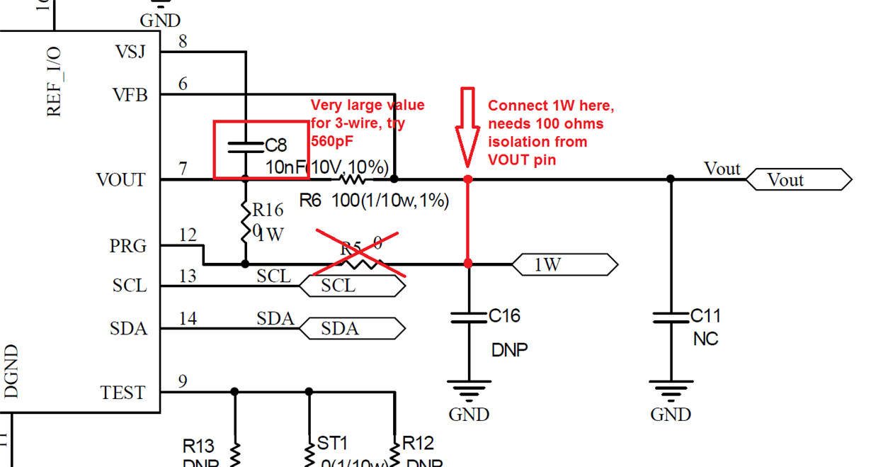
  • I've also found some issues with your schematic that are likely causing the errors in 3-wire mode. Please see the image below.

    Best regards,

    Ian Williams