This thread has been locked.

If you have a related question, please click the "Ask a related question" button in the top right corner. The newly created question will be automatically linked to this question.

INA217 single supply

Other Parts Discussed in Thread: INA217, OPA2137

Hello,

I'm working on a pre-amplifier using the INA217, but I couldn't get a linear operation for Vout. I saw that I can use this op-amp as single supply, but I can't make that work. Any suggestion? 

  • Hi Carla ,

    I suspect you are having a common mode issue

    Can you please share the schematic ,

    Please ensure that the schematic includes the supply voltage , the common mode voltage and reference voltage clearly marked.

    Regards

    shreenidhi

  • Hi Shreenidhi,

    First, when I made the following circuit, I did not get the gain from the datasheet, which was G=1 + (10k/RG).

    I used a symmetric source made from a two channel voltage supply to provide the +5 and -5 V, and Ref and Vin-  connected to the virtual ground, as shown in the figure.


    Is that right or a I made something wrong? If it's right, why didn't I get the gain equal to 2?

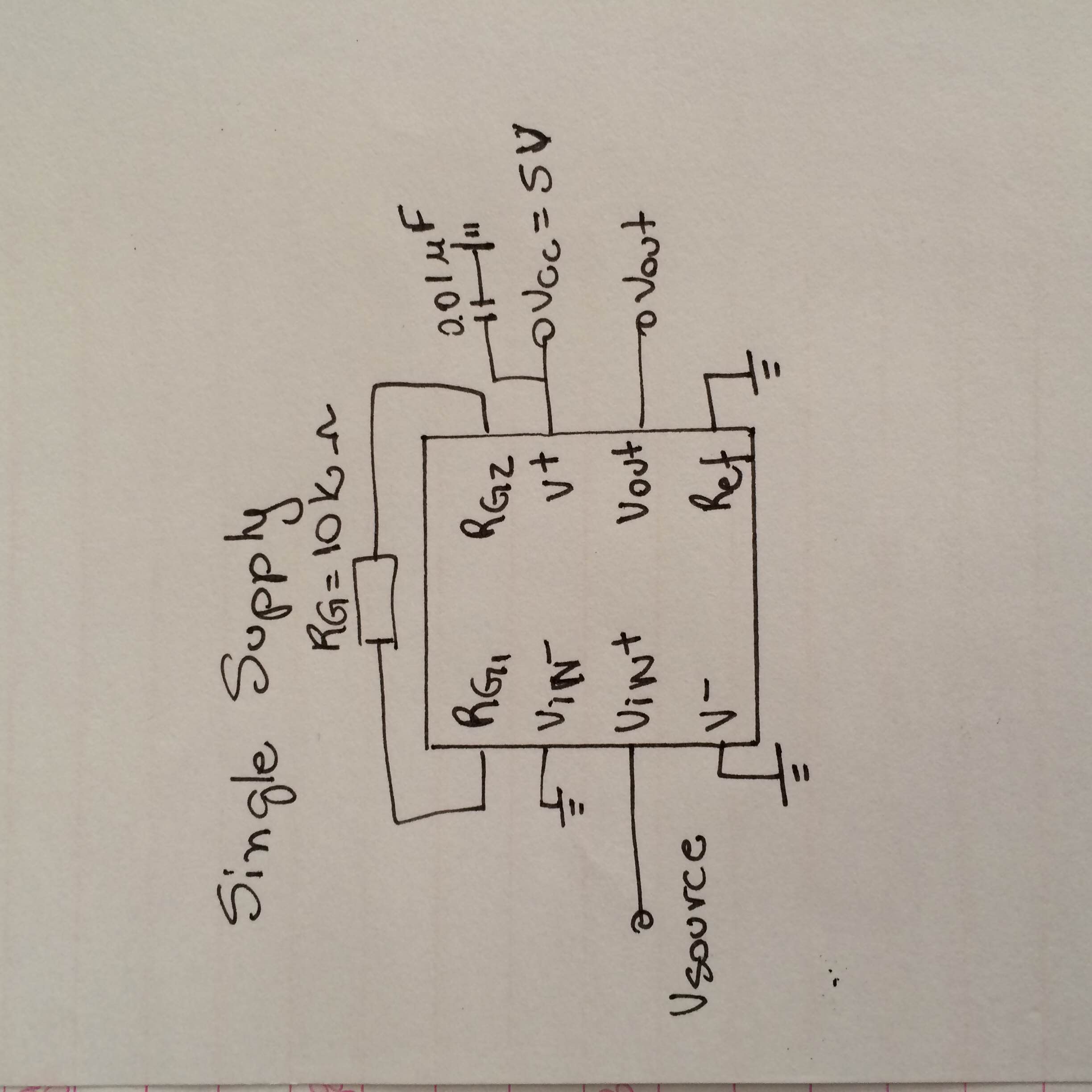
    Second, for the Single Supply Voltage, I used the following circuit. 

    Again, I used RG=10k ohms to make the gain be 2. And I used Vcc=5 V, the values from Vin wil be varying between 0 and 2 V, so I think I'm not going to have problem with saturation.

    Thanks in advance,

    Carla

  • hi Carla.

    Thank you for the quick and elaborate reply

    The 4th  sentence of the data sheet reads the device works from +/- 4.5 to +/- 18V

    Hence for the device to used in single supply the V+ should be atleast equal to 9V

    Thus the single supply case shown above is not possible as you have mentioned with INA217 as V+ is only 5V

    The input common mode  range for the INA you have used is given below

     positive rail direction  = (V+)  -  4V

    negative rail direction = (V-)    + 4V

    The output limitation is given below

    (V+) - 2 V

    (V-) +2 V

    Case 1

    for a +/-5 V supply as you have mentioned in case 1 , 

    for the output to be linear with respect to your input  , the output needs to be between  -3V  to +3V only

    And your input needs to be -1V to +1V only


    As you are supplying a signal of 0  to 2 V with a gain of 2 ,

    your are violating both the conditions (input and output)

    Hence you are not able to get a linear relation between input and output which is making it appear like your gain is not equal to 2

    Case 2

    for a +5 V and GND  supply as you have mentioned in case 2 , 

    for the output to be linear with respect to your input  , the output needs to be between  +2  to +3V only

    and the input common mode range is violated in all cases

    Hence device cannot be used with a +5V single supply as mentioned earlier

    hence i would recommend using a INA in which the common mode voltage range is not violated and output is also within the specified range

    Also you can tweak your inputs as shown below to make sure you are not violating the input common mode range


    Regards

    Shreenidhi  


  • I'm sorry but I didn't get the values that you mentioned for the input and output range in all cases.

    In my understanding, in case 1, if I use +-5 V supply, I expect a maximum output voltage range of +-5 V, but you said that it needs to be between -3 to 3 V. Could you please show me how you found those values? And also, I don't understand the limitation on the input values.

    Sorry, I'm a beginner :)

  • Hi Carla,

    In electronics all of us are beginners ,  always 

    No need to feel bad about it :)


    I would recommend you to watch a 10 min video at this point of time

    www.ti.com/.../precision-amplifier-precision-labs.page

    Please click on the link above and go through the video on input and output limitations explained wonderfully by my colleague


    I believe the video will help you understand clearly the common mode limitation issue

    Regards
    Shreenidhi

  • Hello Shreenidhi,

    I watched the video and I fully understand what was going on with my circuit! Thank you so much for you help (and the video that is super detailed!)

    However, I took a look at another component's datasheet - http://www.ti.com/lit/ds/symlink/opa2137.pdf  - and I don't have a max value for Common-mode voltage range.. I have only (V+)... does that mean any default range or something like that? 

    Thank you again!!!! Sorry for being detouring the post.

  • Hi carla,
    No problem, we are always glad to help you

    So the datasheet of opa2137 mentions common mode input stage as( V-)+3 V to V+

    V+ here means the vcc or the positive supply you have connected to the op amp

    For example
    If say op amp is connected to +/-10V

    The input common mode range is - 7 to +10 volts

    Regards
    Shreenidhi
  • Thank you so much!

    Regards

    Carla