This thread has been locked.

If you have a related question, please click the "Ask a related question" button in the top right corner. The newly created question will be automatically linked to this question.

LMV358 Vout

Hello,

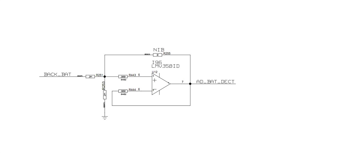
My customer application is as below, they use scope to test the voltage between R251 and R443, they also test the pin7 voltage of our part, they find the voltage of pin7 is about 0.2V higher than input. Can you help to give your comment?

Regards,

Nanfang

  • Nanfang,

    Please attach the schematic again.
  • Nanfang,

    If R255 is zero ohms then the input and output have to be the same, but the circuit would not be useful.

    If R255 is open, then output will follow (be the same as) the input.

    However this is true when VCC is on and input is greater then 0 and less than VCC - 1V.

    What is VCC and node voltage?

  • And don't forget the loading of the scope probe, usually 10Meg for a x10 probe, and 1M for a direct scope input.
    Probing the input will place the 10M scope probe in parallel with R253 (2MEG). Does the ADC reading change when the scope probe is applied?

    Regards,
  • Hello Ron,

    Customer doesn't solder R255 on their board, and Vcc is 3.3V, what is node voltage? do you have any comment? thanks

    Regards,

    Nanfang

  • Hello Paul,

    Yes, customer place the 10M scope probe, when the scope probe is applied, they find the ADC reading change small. So do you have any suggestion how to test the voltage?

    Regards,
    nanfang
  • Hello Nanfang,

    They need to use a high impedance DMM, or, compensate for the known voltage divider formed by 2M//10M.

    Note that almost all hand-held DMMs, and many low cost bench DMMs, have a 10Meg input resistance. Some high-end DVM's have >gigohm input resistance (but some need to be manually switched into gigohm mode, like the HP/Agilent 34401, and it is only gigohms for <=2V range). Be sure to verify the input resistance (usually mentioned on the back of the meter).

    Placing the scope probe on the positive input places 10M in parallel with the 2M resistor, changing R253 to the equivalent of 10M//2M=1.6667M, thus changing the divider ratio, and lowering the voltage on the positive input pin.

    The negative input is driven by the output, so it is lower impedance and not affected by the 10M probe load.

    So the voltage will drop on the positive pin when probed, and will not drop on the negative pin (and output) when probed. So the positive pin will *look* like it is lower when probed individually.

    You can use another op-amp as a follower to provide a high impedance buffer, or, just know that the probe is causing the difference and re-calculate the expected voltage ratio with R253 = 1.6666Meg.

    Regards,