This thread has been locked.

If you have a related question, please click the "Ask a related question" button in the top right corner. The newly created question will be automatically linked to this question.

TLC372 failing into permanent "LOW" state.

Other Parts Discussed in Thread: TLC372

I have a design that uses the TLC372 comparator. This is a legacy design for my company that I inherited that has about 15 years of pedigree. I'll admit there are conditions where the input voltage is greater than the supply voltage of the comparator, but based on my analysis we have enough impedance to satisfy the requirement of limiting the input currents to 5 mA.

We recently had a new application of our system and had two separate failures with very low hours. In both instances the "B" side of the comparator is exhibiting a permanent "LOW" output. What threats could cause this failure mode? Are we damaging the output section or the input section? Would the failure mode tell us if the damage is on the inverting or non-inverting input?

  • Hi Llyod ,

    Welcome to TI E2E .
    I will move your post into precision amplifiers forum for support.
  • Hi Lloyd,

    Usually when a comparator's output gets permanently stuck in one state it is because an input has been damaged. They are exposed to the input levels, sometimes in situations that involve signals from an external environment. If something such as an electrical over-stress (EOS) event occurs, they can be damaged. The output is usually isolated from such conditions. The TLC372 has push-pull outputs so they may not even have a pull-up, or pull-down, to a supply line. 

    Can you share the TLC372 circuit portion in which the failures are occurring? We need to know what levels are being used at the inputs, what the source of those inputs are, and the supply source/voltage being used.

    Regards, Thomas

    PA - Linear Applications Engineering

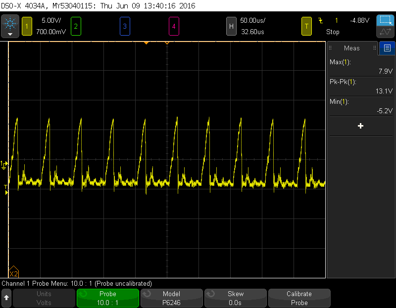
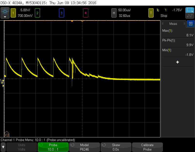
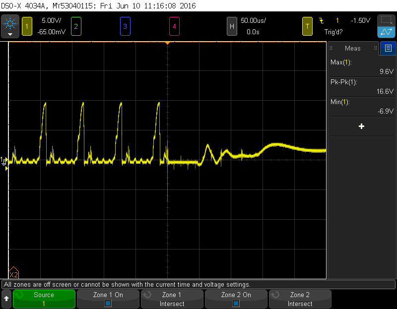
  • Pin 1

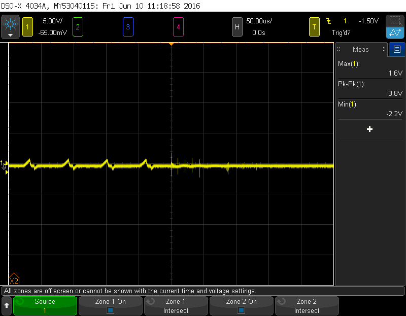
    Pin 2

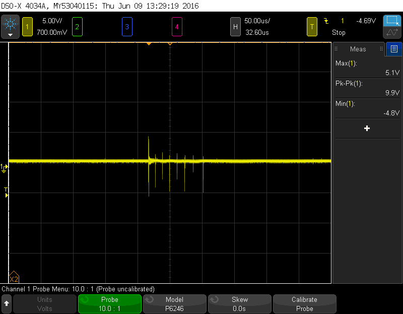
    Pin 3

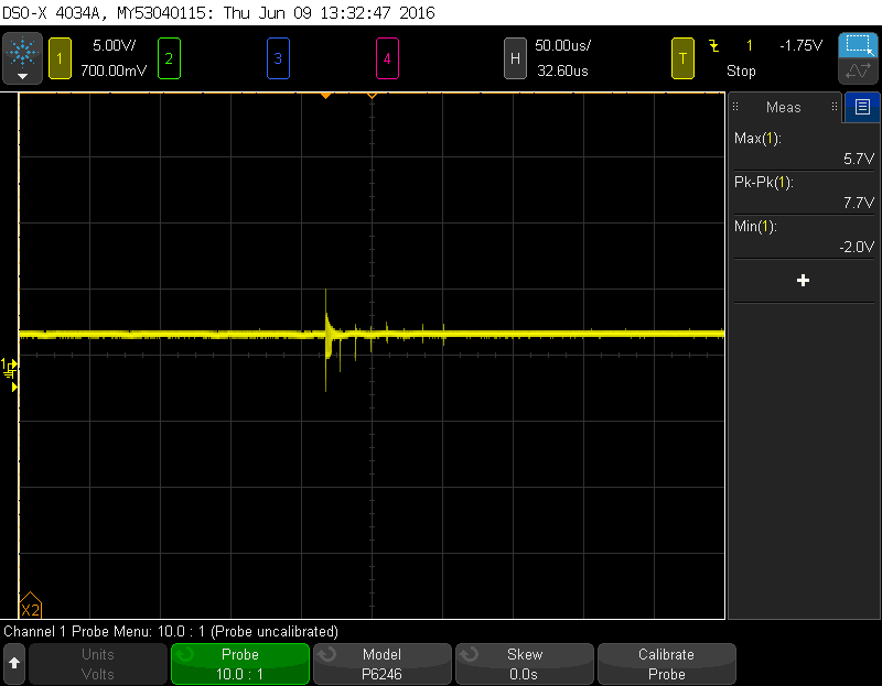
    Pin 5

    Pin 6

    Pin 7

    Pin 8

  • Here are screenshots of the voltages across each pin with respect to the comparator ground pin under typical steady state input conditions. The comparator is supplied with 8vdc. Measurements were taken with a 400Mhz differential probe at the pins where they enter the comparator casing. I cannot post schematics in a public forum like this although I could possibly email it to you.

    It should be noted that both components have failed on the "B" 5-6-7 side of the device.

  • Hi Lloyd,

    Please send the TLC372 schematic to my email address listed below. I will treat it as confidential.

    Regards, Thomas

    PA - Linear Applications Engineering

    kuehl_tom@ti.com