This thread has been locked.

If you have a related question, please click the "Ask a related question" button in the top right corner. The newly created question will be automatically linked to this question.

REF 1933 and op amp current requirements

Other Parts Discussed in Thread: REF1933, OPA350, TINA-TI, OPA376

I'm contemplating using a REF1933 3.3/1.65 reference to power an op amp circuit (OPA350 as an example). I anticipate an input voltage of 5V for testing and eventually 3.7V in practice. My questions are these:

Are the stated output current values of the REF sufficient for 3.3V (single-sided) supply to the OPA 350 and 1.65V for an offset bias under normal operating conditions for the OPA 350.

If not, is it possible to follow the REF output with something like a BUF 634 (assuming of course a high enough voltage for the 634's supply), or some other suitable op amp in voltage follower mode ?

Are there better solutions for such a configuration ?

The input to the system will be a geophone (oscillating coil subject to ground shaking).

  • Moving to amplifiers E2E

  • Bob,

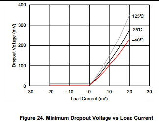
    The minimum output current of REF1933 is specified to be +/-20mA but in order to answer your question, please provide detailed schematic of your circuit application.  To decide if you have enough voltage supply headroom for the proper operation of the circuit under given load, you need to consider REF19xx dropout voltage (see below) and OPA350 minimum supply voltage of 2.7V

  • The circuit I've simulated using Tina-TI is shown below. I would like initially to supply the REF 1933 with 5V, and use the two outputs with theOPA 350 as indicated, 3,3V to the positive rail, 1.65V to the positive input as a reference to center the output at 1.65 V.

  • Bob,

    Below please see my asnwers:

    Are the stated output current values of the REF sufficient for 3.3V (single-sided) supply to the OPA 350 and 1.65V for an offset bias under normal operating conditions for the OPA 350.

    The minimum specified output current of REF1933 is +/-20mA thus it is much more than enough to drive OPA350 as long as you don't connect OPA350 output to a heavy resistive load.

    Are there better solutions for such a configuration ?

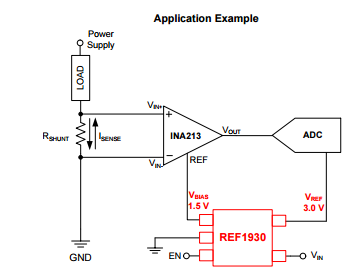
    I do not understand the need in your configuration to drive OPA350 supply voltage with exactly twice the voltage of the non-inverting input - it will work even better to just use 5V supply to power OPA350.  This is not the same situation as what is shown in case of driving ADC below where in order to maximize dynamic range of ADC the REF voltage of INA must be exactly in the middle of ADC REF voltage.  

    Also, if you really need DC precision (initial accuracy and temperature drift) of REF1933, you would probably be better off to consider instead of OPA350 higher precision OPA376 (500uV vs 25uV max offset, 4uV/C vs 0.26uV/C  typ drift, respectively) unless the input noise or driving large capactive loads are your  primary concerns.


  • Hi Marek,

    Thanks very much for the reply. I'm aware of the usual use of the REF1933 as you described in the accompanying diagram. The output of my prototype circuit will be an A/D converter on an Arduino board with A/D input voltage limited to 3.3V, hence the 3.3V ceiling on the positive rail of the OPA350 opamp. My interest in the REF1933 came from the fact that both 3.3V and 1.65V regulated voltages are available from the same IC. I'm assuming that the load presented by the A/D converters of the Arduino would not draw too much current from the 3.3V supply provided by the REF1933 to the OPA350. I'll give the prototype a try and see what happens.