This thread has been locked.

If you have a related question, please click the "Ask a related question" button in the top right corner. The newly created question will be automatically linked to this question.

TLV1701 comparator very strange behavior (nightmare edition)

Other Parts Discussed in Thread: TLV1701

I have a requirement to make a circuit that can transmit some high voltage logic signals, and can also sense those signals and verify what was sent. The HVIO output toggles between Veh+ and Veh- to make HV logic. The output works correctly, the sense part of the circuit works correctly below Veh+ = 30V, then things get strange. I have no idea how to diagnose what is going on, or why a comparator might do this sort of behavior.

The rest of the circuit is very complicated, and also top secret so I can't show it. But trust me that all the signals here are DC except for HVIO (that is my input signal) and Comp Out (the output signal to uC). Comp Pwr is 30V, Vref is buffered 50% Veh+. Veh- is ground

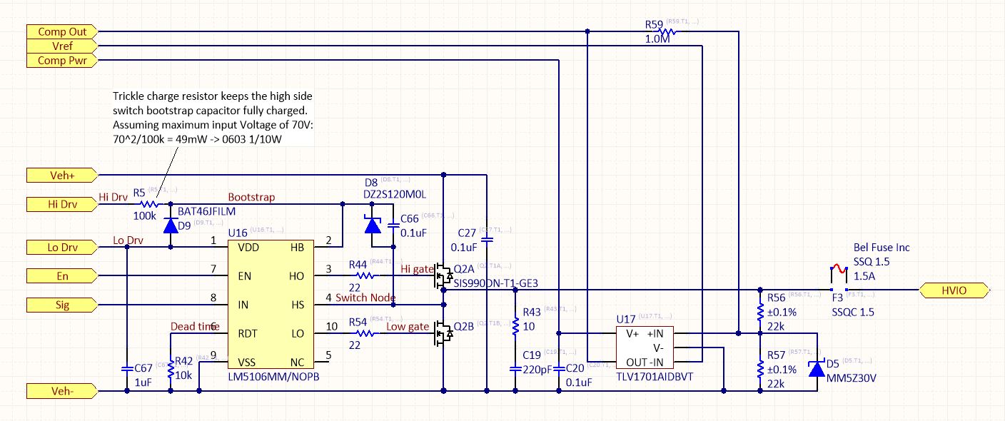
Picture 1 is the schematic.

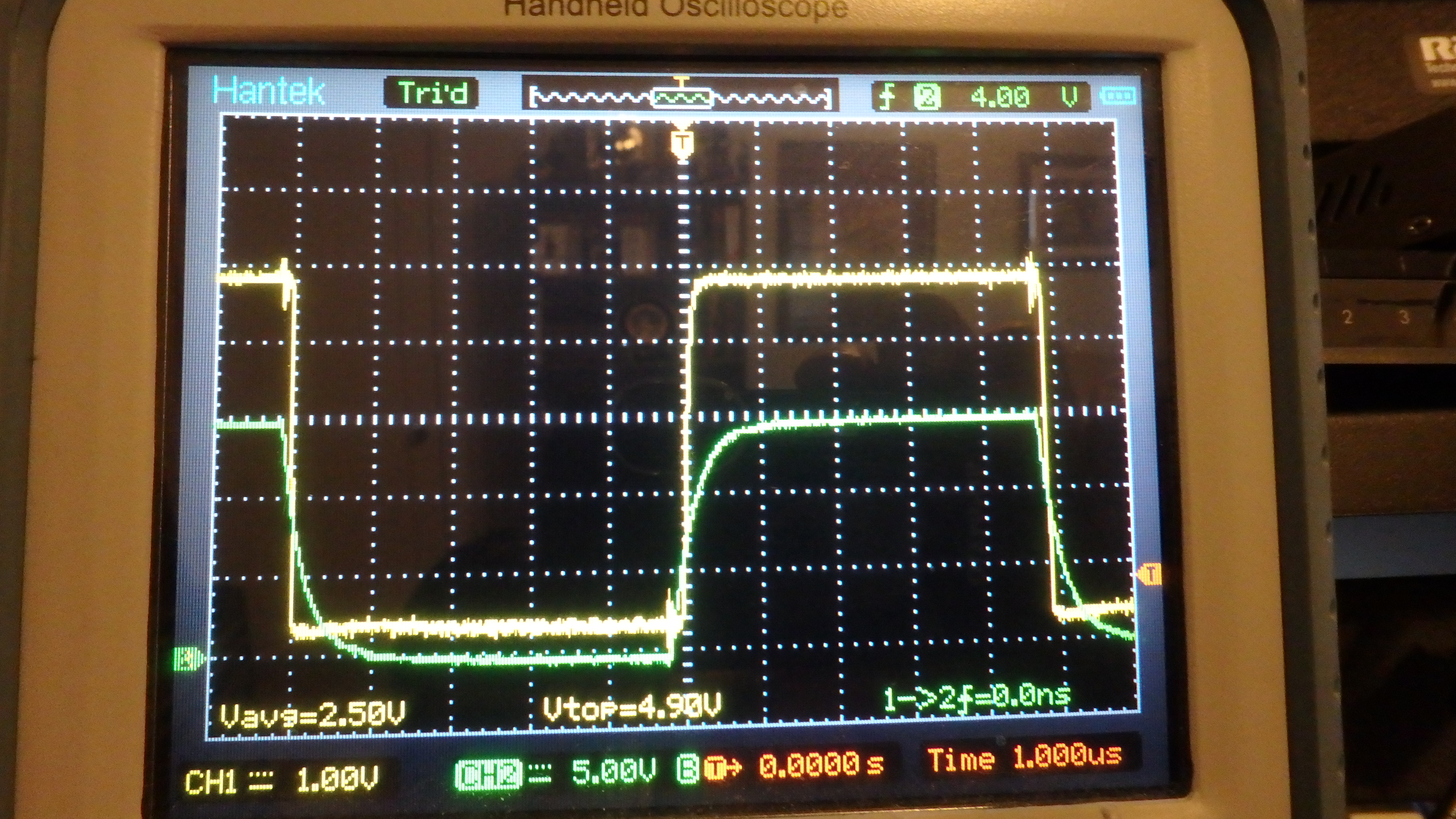
Picture 2: Green is the IN+ on the TLV1701, Yellow is the OUT. Its measured at the terminals. You can see IN+ is a divided HVIO. HVIO is toggling between 0 and Veh+ (30V in this image). Yellow is toggling as Green passes the 50% Vref threshold. It's working perfectly here, exactly as I expect.

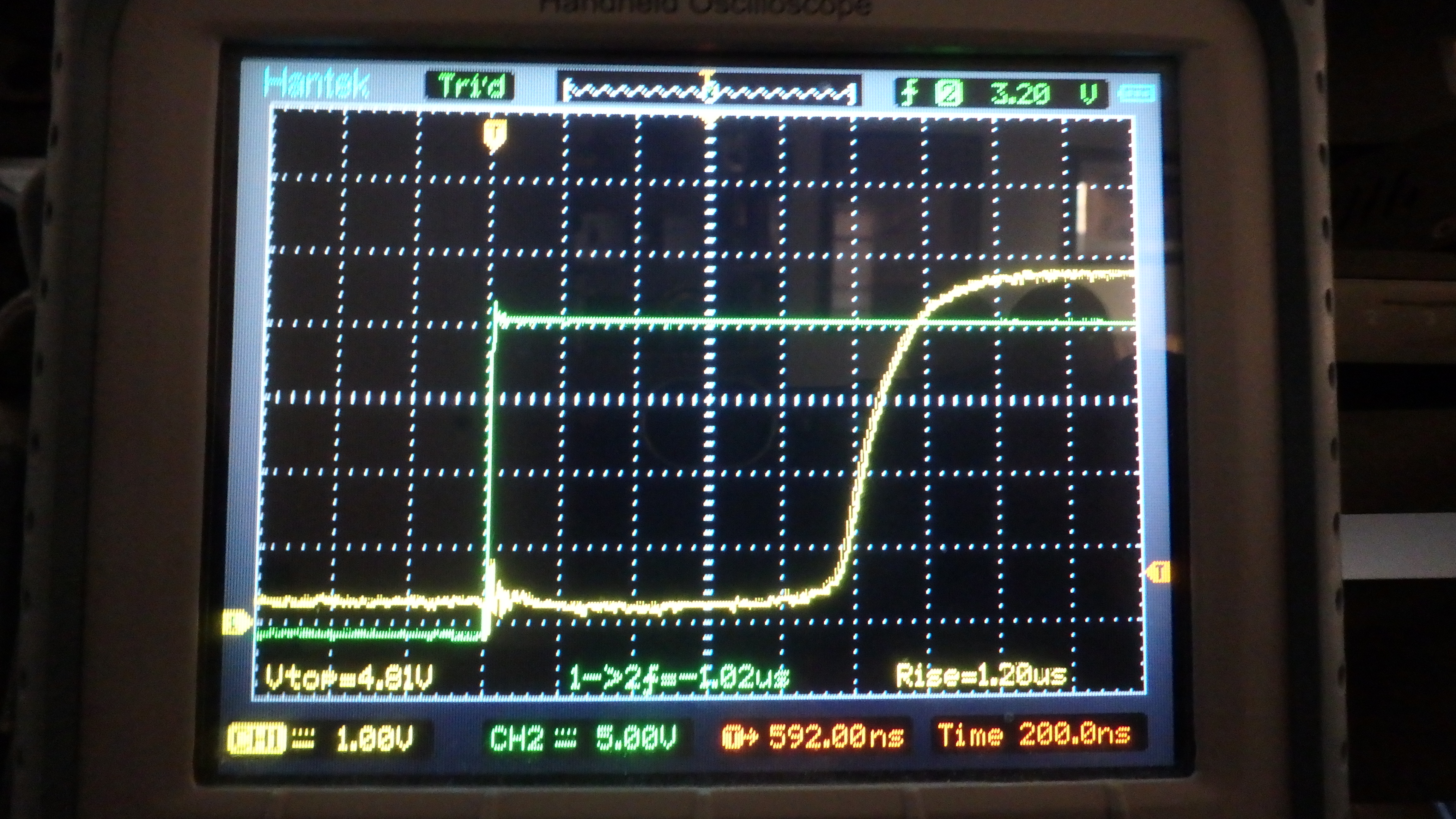
Picture 3 is what happens when I turn Veh+ from 30 to 40V. Now yellow has an extra 1us delay for some reason. Why would the comparator add a delay when Veh+ is 30 to 40V?

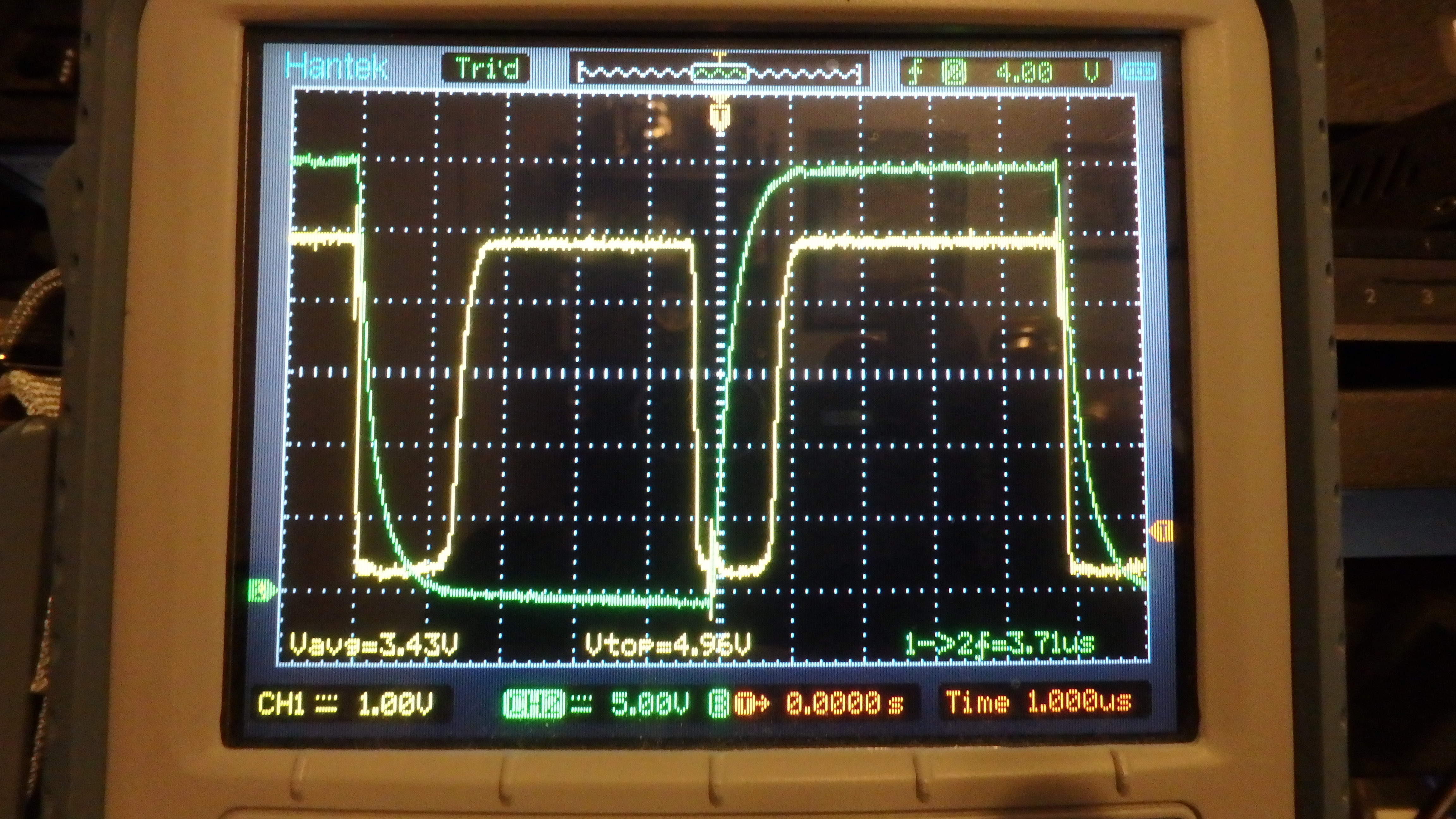
Picture 4: Turned the voltage up to 55, and the rising delay partially goes away, but now there is a random toggle 1us after green goes down.

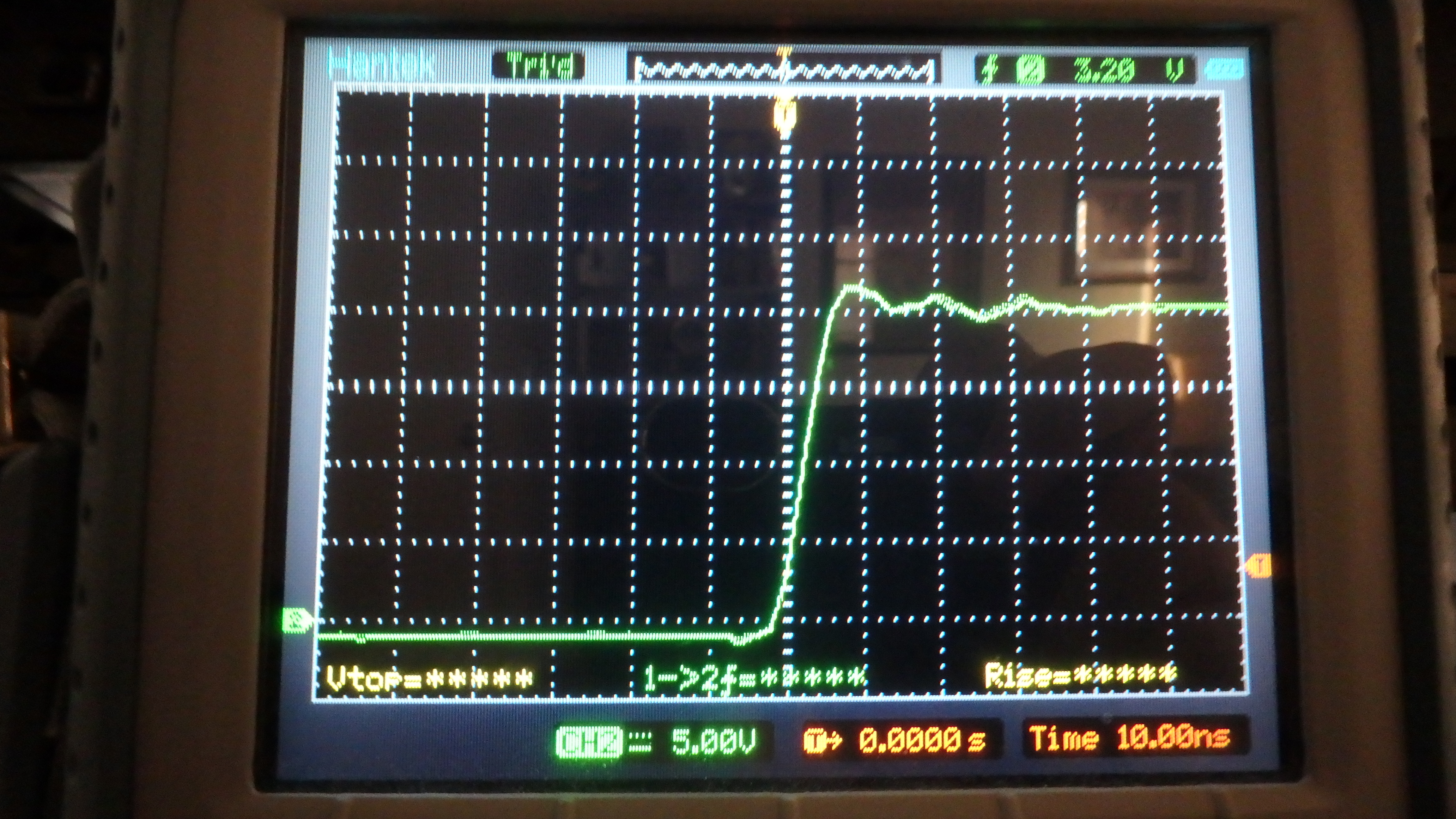
Picture 5: Turned the voltage up to 60, and the random toggle stays toggled for almost the entire off period of the input signal. Why would a comparator do this?

  • Hi Nick,

    Thanks for the excellent write-up and the images describing and showing what you are observing in your TLV1701 circuit. I don't find anything about your circuit that would explain the odd behavior you are observing. 

    We are going to set the comparator portion of your circuit up on the bench and see if we can duplicate these results. Can you provide us the Vref level?

    Regards, Thomas

    PA - Linear Applications Engineering

  • Thank you for looking into it! Vref is supplied by a buffered 1/4 divider from Veh+. So for Veh+ = 30V, Vref = 7.5V. For Veh+ = 60V, Vref = 15V. The output is pulled to 5V with a 2.2 kOhm resistor.

  • Hi Nick,

    There is a 1MOhm resistor around the out and in+ pins, possibly to add hysteresis. I'm suspecting that the time constant added by the RC (input capacitance) network is causing these glitches. Have you tried removing the resistor and checking again?

    Regards,
    Sudarshan
  • I did try removing the resistor. It doesn't seem the change the behavior.

    Next, I am going to try putting a 100pF capacitor in series with R56 to see if lowering the source impedance to +IN helps.

  • Hi Nick,

    A quick update. We are configuring a PC board to accommodate your TLV1701 application circuit. Also, we just came up with a way to get the required 60 V Veh+ digital level. None of our generators will do that directly.  It's going to take us a little more time to get everything playing together, but we should be set later today, or early tomorrow. I'll let you know what we find.

    Regards, Thomas

    PA - Linear Applications Engineering

  • I have an additional clue. I attempted to lower input impedance two independent ways. 

    1) Add 100pF capacitors in parallel with 22kOhm R56 andR57. This should allow extra charge to flow through on the rising and falling edges.

    2) Change R56 and R57 to 2.2k resistors instead of 22k. (Without the capacitors)

    The result both times: the Voltage at which the delay changes appear is lower. The delay in picture 3 now begins to appear at 20V instead of at 30V.

    Here is a picture of my 20V input waveform (no BW filter on scope):

    Here is the delay at 18.6V Veh+ (R56, R57 = 2.2kOhm):

    Here is the delay at 20.4V input (R56, R57 = 2.2kOhm):

  • Hi Nick,

    Where are you measuring the square wave of the blue waveform from? From the signal generator or straight from the Vin+ pin of the TLV1701? We are having trouble producing a waveform with such a fast rise time with the resistors and parasitic/input capacitance of the circuit.

    Thanks,
    Raymond Barakat
  • I am measuring the input at the function generator in my previous post. I calculated the capacitance at the terminal of the TL1701 (in this circuit) to be 33pF.

    Using the original 22k input dividers, there is a slower RC than using 2.2k dividers. Using a 100pF capacitor divider in parallel with R56 and R57 the rise time is very fast, but the division is not quite 50%.