This thread has been locked.

If you have a related question, please click the "Ask a related question" button in the top right corner. The newly created question will be automatically linked to this question.

INA129 Gain is not linear

Other Parts Discussed in Thread: INA129, AMC1200

Dear,

I have two questions about the operation of INA129P:

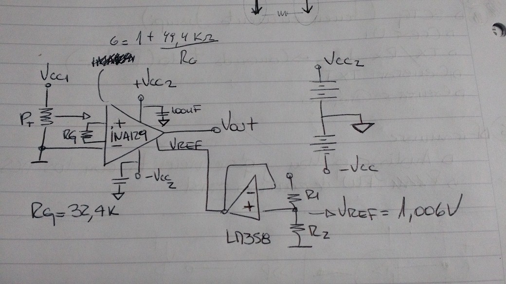
1) The gain equation for this AO is G = 1 + (49K2 / Rg), we are setting to Rg = 32K4 so the gain must be 2.54. For an input voltage range from 0,034V to 1.6V the gain varies from 1.21 to 1.32. The reference voltages is 1,006V.  Why this difference?

2) The gain is not linear for 0,029V or lower. It change from 1.32 to 1,14. Where is the problem?

I attached the circuit.

Thanks in advance.

Regards,

  • Hello Carlos,

    Here are some questions/observations for you:

    1) What are the supply voltage(s)?
    2) Please make sure that you are measuring the input voltage, reference voltage, and output and the physical pins of the device. By this I mean that you should literally touch the probe of your measurement equipment to the pins of the device. This eliminate potential issues due to anything except the device.
    3) Similarly, have you tried disconnecting the sensor and using some other method to provide the input? This eliminates potential issues due to the signal source.
    4) Is this circuit built on a PCB? I generally recommend using a PCB because it minimizes potential errors due to wiring or parasitics. Note that you can use the INAEVM-SO8 to evaluate the INA129.
    5) Given that there is a reference voltage, I suspect that you may be operating the device with a single or unbalanced supply. If so, this is likely a Vcm vs. Vout issue. If that is the case, try using +/-15V supplies. If the gain non-linearity goes away then it is definitely a Vcm vs. Vout issue. For more information on this relationship, please see the following FAQ:

    e2e.ti.com/.../3373.understanding-instrumentation-amplifier-vcm-vs-vout-plots

    Please note that I will be out of the office from tomorrow until 7/11, so hopefully we can get this resolved today.
  •  Hi Pete,

    1) Supply voltages are:

    Vcc1  = 3V

    Vcc2 = +5V / -5V

    2) Yes, we are measuring over the pins.

    3) Vcc1 and Vcc2 are different sources with different grounds, you can see on the schematics (posted in nº1) the different grounds. Well, when we connect the circuits in that way, the problem was as we detailed before. Now, if we use only one source, for example Vcc1, the gain is 2.54. As the nature of the application of the circuit, we need to use separated grounds. The sensor circuit, Pt (potenciometer), generate a differential voltage with referred to Ground 1. The rest of the circuit use Ground 2.

    4) Yes, but not routed, it is an experimental board.

    5) We have just finished  read the articles you suggest to us. We think that Vcm vs. Vout issue fit here. Well, as I told you, the nature of our application need to read a differential voltage with a different ground. The end application is very similar  to measure a voltage with a multimeter. So, is not useful INA129 for our application?

    Thanks in advance for your help and time.

    Carlos

    Elefante Embebido

  • Hello Pete,

    We have read again the note that you suggested to us and now we are sure that the issue is the common mode voltage. 

    The image below shows the limits of INA129:

    Our supply voltage is +5V / -5V, the output voltage range is 0 to 3.3V and reference voltage is 1.65V. The gain is 2.54 but we consider to change it to 16.44 (RG = 3.2K). If consider figure 6, the maximum common mode voltage is near to 2V for Gain = 2.54 and close to 3V if the gain is 16.44. Is that right? 

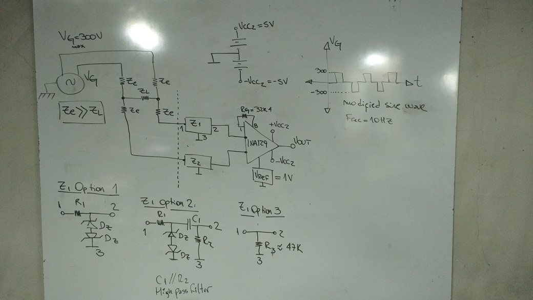
    As we told you, we need to measure a floating voltage. The following circuit describe the situation:

    Over ZL the maximum voltage is 100mV in normal operation. 

    We have Thought 3 different option for the input circuit:  

    Option 1:

    The zenner protect the INA from any over voltage and we think that depends on the value they will limit the common mode voltage to keep our INA inside the limit of the figure 6. Is that correct?

    Option 2:

    Idem option 1 and we add a high pass filter in order to "clean" the signal and provide a DC path from the instrument amplifier inputs to the instrument amplifier ground. 

    Option 3:

    Provide a DC path from the instrument amplifier inputs to the instrument amplifier ground.

    What do you think about that options?

    Are we in the correct way?

    Is suitable the INA129 for this application?

    Thanks again for you time and effort.

    Carlos

    Elefante Embebido.


  • Hello Carlos,
    I have returned from my vacation and will reply tomorrow.
  • Hello Carlos,

    Thanks for your patience and additional information. I did not notice the different grounds in the original schematic. Now that I understand a little more about your application, perhaps you'd be interested in a different device: AMC1200. The AMC1200 is a fully-differential isolation amplifier. One concern, however, is that the input voltage range is +/-250mV. It looks like your differential voltage is +/-300mV. If that can be adjusted, the AMC1200 will apply a gain of 8V/V to the input differential signal. The output stage can be supplied with a single 5V or 3.3V supply and the output signal will be centered around 2.55V or 1.29V, respectively. The working voltage should be plenty for your 300V common-mode input signal. If you think this will solve the issue and would like more information, please let me know so I can move the post to the appropriate forum.
  • Hello Pete,

    First of all thanks for your time and the clarity of concepts.
    We agree with you that we should try with the AMC1200. We have requested some samples to test it in our application.
    Next week we will contact you to give a feedback.

    Thanks again,

    Carlos

    Elefante Embebido.
  • Hello Carlos,

    Glad I could help!  Please let me know the results.

  • Hi Carlos,

    I've split this thread where the discussion changes from the INA129 to the AMC1200 and will move this back to the amplifier forum for future reference.