Other Parts Discussed in Thread: INA226, BQ24040
This thread has been locked.
If you have a related question, please click the "Ask a related question" button in the top right corner. The newly created question will be automatically linked to this question.
Other Parts Discussed in Thread: INA226, BQ24040
Hi Idan,
Section 7.5 of the datasheet explain how to determine the Current LSB step by step. Everything that is on the calculations tab of the EVM GUI (LABVIEW) is explained in that section. The MAX current depends in your application.
In addition to this we have a training Video that explain the calculations as well:

Also, I am attaching a Excel Spreadsheet that contain all formulas needed. 6683.INA226_Cal_workbook.xlsx
Hope this helps,
 I can not understand why I get totally incorrect measurement results, which is doesn't make sense at all..
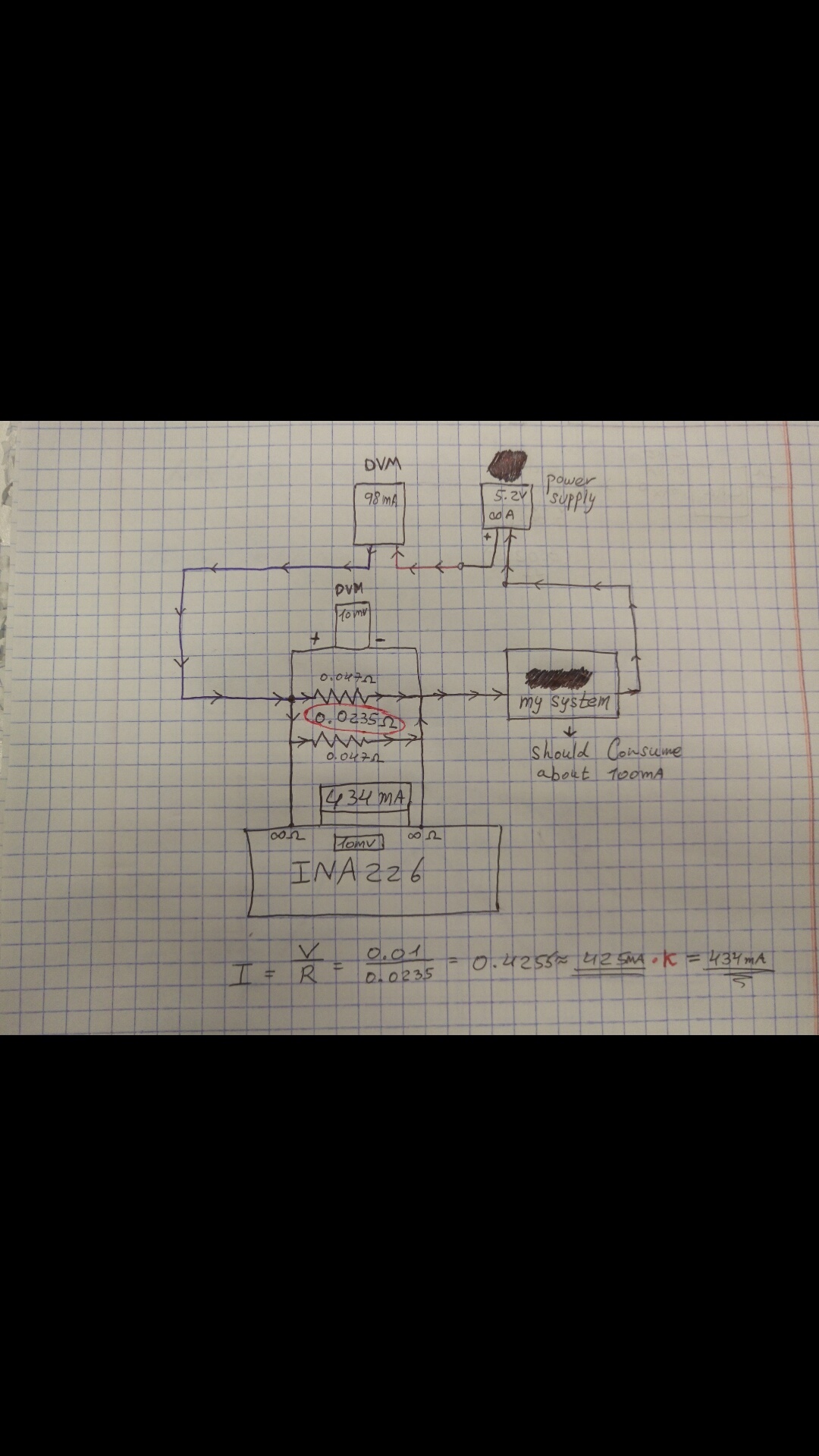
my DVM (which i trust) give me result of 98mA (really close to the actual measurement -> 100mA) VS. the INA226 module that giving me 434mA.
again, I do know what my maximum current consumption (Through a charger chip which is 0.8A max, BQ24040 datasheet) and I set it to 0.8, Current LSB to 25uA
Hi Idan,
Can you confirm the following?
What is the current reported back by INA226? 434mA?
The drawing shows a DVM measurement of Vshunt to be 10mV, is this correct? If so the two measurements agree and the problem is not with INA226.
If both (1) and (2) are correct, you may still be suspecting that INA226 is somehow causing the large 10mV reading, then uninstall INA226, make a DVM measurement to see if the 10mV still exists. If it does, the resistance between the measurement terminals is probably not as small as you expected. This may be caused by layout, soldering etc.
If only INA226 is reporting back the wrong current value, please share all relevant settings/readings, including Current LSB; CAL register(05h) value; Shunt Voltage register(01h) reading; Current register(04h) reading.
Another note: The sense resistor you chose is too small, let alone when you put two in parallel. While this is probably not the cause of the problem and nothing prevents you from doing this, it does limit the dynamic range. An optimal resistor value is one that enablse full input range at the maximum expected current level. As an example, if the MAX expected current is 100mA, a sense resistor that is between 0.5 and 0.8 Ohm is a better choice unless the system can't tolerate a 50mV drop.
For the same 100mA MAX expected current, I would choose current LSB to be 10uA; then with a 0.5Ohm resistor, CAL register value would be 1024 according to equation (1) in the datasheet.
Regards,
Guang-Apps CS Products