This thread has been locked.

If you have a related question, please click the "Ask a related question" button in the top right corner. The newly created question will be automatically linked to this question.

Interface USB for connection to LMP91000EVM

Other Parts Discussed in Thread: LMP91000EVM, LMP91000, MSP430F5528, ADC161S626, LMP91002, MSP430F5529, MSP-EXP430F5529LP

Good morning everyone!


I would like to use LMP91000EVM for measuring signals of a capacitive cell.

How can I adapt the JTAG target connector (http://www.ti.com/tool/MSP-FET430UIF) to the SPIO-GPSI16 connector (http://www.ti.com/tool/LMP91000EVM)?

I need to connect to LMP91000EVM card into a USB port of a PC to use the interface Sensor AFE for LMP91000EVM without an SPIO-4.

Figure 1 - MSP-FET430UIF and LMP91000EVM.

Figure 2 - JTAG target connector pins and SPIO-GPSI16 connector pins.

Figure 3 - Sensor AFE screen.

I checked the Application Note http://www.ti.com/lit/an/snaa138c/snaa138c.pdf with use of MSP-FET430UIF, but there are no more specific information in this document.

Could anyone help?

I checked on the integrated circuit page LMP91000 (http://www.ti.com/product/LMP91000/toolssoftware) that there is a link (http://www.ti.com/lit/sw/snac032/snac032.zip) providing 4 examples, and the code example demo-app04.
The main.c uses 6-pin MSP430F5528 for communication:

//                               MSP430F5528 
//                              --------------------------
//                         /|\  |                           XIN|-
//                          |   |                                 | 
//                          --  |RST             XOUT |-
//                              |                                 |
//                              |     P3.0/UCB0SDA|<--> SDA....................................................(to pin 11 in SPI-GPSI16)
//                              |     P3.1/UCB0SCL|--> SCL........................................................(to pin 12 in SPI-GPSI16)
//                              |                                 | 
//                              |                         P2.6|<-- MENB....................................................(to pin 8 in SPI-GPSI16)
//                              |                                 | 
//                              |   P4.5/UCA1SOMI|<-- ADC16S626_SDO...............................(to pin 5 in SPI-GPSI16)
//                              |     P4.0/UCA1CLK|--> ADC16S626_CLK................................(to pin 3 in SPI-GPSI16)
//                              |                         P2.4|--> ADC16S626_CSB................................(to pin 1 in SPI-GPSI16)

My doubt in MSP-FET430UIF is:
What are the pins to be used in JTAG target connector? 10, 12, 14 and...?

Regards,

Luiz.

  • Good evening everyone!

    Correcting the previous suggestion pins SPI-GPSI16 connector, I2C communication uses the following pins:
    11 - SDA
    12 - SCL
    8 - MENB
    These are used to set the amplifier parameters.

    The SPI communication uses the following pins:
    5 - SDO
    3 - CLK
    1 - CSB
    These pins tell the MSP430F5528 microcontroller the amplifier analysis of values converted to digital data.

    Source:
    14 - Positive
    2 - Negative

    Someone confirm this information?

    Regards,

    Luiz.

  • ...There remains the question of the pins MSP-FET430UIF:

    10 - SPI_CLK / I2C_SCL
    12 - SPI_SOMI / I2C_SDA
    14 - SPI_SIMO

    Source:
    4 - Positive
    9 - Negative

    SPI and I2C simultaneous?

    Chip Select (CS) is not necessary?

    Regards,

    Luiz.

  • main.c of the demo-app04

    //******************************************************************************
    // Description: LMP91000 VOUT Measurement (No sensor: Vout = 67% of VREF = 1.67V)
    //
    // Demo Application for MSP430/LMP91000 Interface Code Library v1.0
    // This is a new example using LMP91000EVM (not LMP91000SDEVAL) and the onboard ADC161S626.
    // Code is applicable to both LMP91000 and LMP91002 devices.
    // LMP91000 VOUT is connected to ADC16S626 as shown in the LMP91000EVM User's Guide.
    // Each conversion result is moved to an 8-element array called results[].
    // The results are averaged and converted. Open a local window in debugger
    // and view the results. Set a breakpoint in the line following vout calculation
    // to see the array of conversion results & measured temperature.
    //
    //                     MSP430F5528
    //                     -----------------
    //       /|\  |                         XIN |-
    //        |   |                                |
    //        --  | RST            XOUT|-
    //            |                                |
    //            |   P3.0/UCB0SDA|<--> SDA
    //            |   P3.1/UCB0SCL|--> SCL
    //            |                               |
    //            |                       P2.6|<-- MENB
    //            |                               |
    //            |  P4.5/UCA1SOMI|<-- ADC16S626_SDO
    //            |    P4.0/UCA1CLK|--> ADC16S626_CLK
    //            |                      P2.4  |--> ADC16S626_CSB
    //            |                                |
    //
    // Vishy Natarajan
    // Texas Instruments Inc.
    // July 2012
    // Built with CCE Version: 4.2 and IAR Embedded Workbench Version: 5.3x
    //
    //******************************************************************************
    // Change Log:
    //******************************************************************************
    // Version: 1.00
    // Comments: Initial Release Version
    //******************************************************************************
    /* Copyright 2011-2012 Texas Instruments Incorporated. All rights reserved.

    IMPORTANT: Your use of this Software is limited to those specific rights
    granted under the terms of a software license agreement between the user who
    downloaded the software, his/her employer (which must be your employer) and
    Texas Instruments Incorporated (the "License"). You may not use this Software
    unless you agree to abide by the terms of the License. The License limits your
    use, and you acknowledge, that the Software may not be modified, copied or
    distributed unless embedded on a Texas Instruments microcontroller which is
    integrated into your product. Other than for the foregoing purpose, you may
    not use, reproduce, copy, prepare derivative works of, modify, distribute,
    perform, display or sell this Software and/or its documentation for any
    purpose.

    YOU FURTHER ACKNOWLEDGE AND AGREE THAT THE SOFTWARE AND DOCUMENTATION ARE
    PROVIDED “AS IS” WITHOUT WARRANTY OF ANY KIND, EITHER EXPRESS OR IMPLIED,
    INCLUDING WITHOUT LIMITATION, ANY WARRANTY OF MERCHANTABILITY, TITLE,
    NON-INFRINGEMENT AND FITNESS FOR A PARTICULAR PURPOSE. IN NO EVENT SHALL TEXAS
    INSTRUMENTS OR ITS LICENSORS BE LIABLE OR OBLIGATED UNDER CONTRACT,
    NEGLIGENCE, STRICT LIABILITY, CONTRIBUTION, BREACH OF WARRANTY, OR OTHER LEGAL
    EQUITABLE THEORY ANY DIRECT OR INDIRECT DAMAGES OR EXPENSES INCLUDING BUT NOT
    LIMITED TO ANY INCIDENTAL, SPECIAL, INDIRECT, PUNITIVE OR CONSEQUENTIAL
    DAMAGES, LOST PROFITS OR LOST DATA, COST OF PROCUREMENT OF SUBSTITUTE GOODS,
    TECHNOLOGY, SERVICES, OR ANY CLAIMS BY THIRD PARTIES (INCLUDING BUT NOT
    LIMITED TO ANY DEFENSE THEREOF), OR OTHER SIMILAR COSTS.

    Should you have any questions regarding your right to use this Software,
    contact Texas Instruments Incorporated at www.TI.com.
    *******************************************************************************/

    #include <stdint.h>
    #include "TI_LMP91000.h"
    #include "TI_LMP91000_register_settings.h"
    #include "TI_MSP430.h"
    #include "TI_MSP430_hardware_board.h"
    #include "TI_MSP430_i2c.h"

    void timerA0_init(void); // initialize timerA0 to generate interrupt every sec
    // for temperature measurement
    #define NUM_OF_RESULTS 8 // Number of temp sensor samples to take
    #define SCALE_FACTOR 3 // For averaging converted samples
    #define ADC16_RATIO 0.07630 // 2500/3268(2500mV ref & 16bit converter, 2s comp o/p)
    #define INTERVAL_1S 16666 // 1sec timer interval
    #define AIN_MINUS 2501 // AIN_MINUS = VREF = 2501mV

    //******************************************************************************
    void main(void)
    {

    uint8_t status = TI_LMP91000_NOT_READY;
    uint8_t read_val[2]; // buffer to store register values

    WDTCTL = WDTPW + WDTHOLD; // Stop watchdog timer

    TI_LMP91000_LED_PxOUT |= TI_LMP91000_LED_PIN; // Set LED ON
    TI_LMP91000_LED_PxDIR |= TI_LMP91000_LED_PIN; // Set pin direction is output

    I2CSetup(LMP91000_I2C_Address); // Initialize I2C module

    TI_LMP91000_MENB_PxOUT &= ~TI_LMP91000_MENB_PIN; // Enable \MENB Pin
    TI_LMP91000_MENB_PxDIR |= TI_LMP91000_MENB_PIN; // Set pin direction is output

    while (status == TI_LMP91000_NOT_READY)
    status = LMP91000_I2CReadReg(TI_LMP91000_STATUS_REG); // Read device ready status

    LMP91000_I2CWriteReg(TI_LMP91000_LOCK_REG, TI_LMP91000_WRITE_UNLOCK); // unlock the registers for write

    LMP91000_I2CWriteReg(TI_LMP91000_TIACN_REG, TI_LMP91000_TIACN_REG_VALUE); // Modify TIA control register
    LMP91000_I2CWriteReg(TI_LMP91000_REFCN_REG, TI_LMP91000_REFCN_REG_VALUE); // Modify REF control register

    read_val[0] = LMP91000_I2CReadReg(TI_LMP91000_TIACN_REG); // Read to confirm register is modified
    read_val[1] = LMP91000_I2CReadReg(TI_LMP91000_REFCN_REG); // Read to confirm register is modified

    if ((read_val[0] != TI_LMP91000_TIACN_REG_VALUE) ||
    (read_val[1] != TI_LMP91000_REFCN_REG_VALUE)) // test values took effect
    while (1); // otherwise error

    LMP91000_I2CWriteReg(TI_LMP91000_LOCK_REG, TI_LMP91000_WRITE_LOCK); // lock the registers
    LMP91000_I2CWriteReg(TI_LMP91000_MODECN_REG, TI_LMP91000_MODECN_REG_VALUE); // 3-lead amperometric cell

    TI_ADC16S626_SPISetup(); // setup onboard ADS14S626 SPI interface
    timerA0_init(); // initialize timerA0 for interrupt every 1sec
    __bis_SR_register(LPM0_bits + GIE); // Enter LPM0, enable interrupts
    __no_operation(); // For debugger

    }
    //------------------------------------------------------------------------------
    // void timerA0_init(void)
    //
    // DESCRIPTION:
    // Initialize timer_A0 to generat 1sec interrupt.
    // Note: This function is for MSP430F5528 & might need modifications for other MSP430s
    //------------------------------------------------------------------------------
    void timerA0_init(void)
    {

    TA0CCTL0 = CCIE; // TA2CCR0 interrupt enabled
    TA0CCR0 = INTERVAL_1S; // Initialize for 1sec interval
    TA0EX0 = TAIDEX_7; // Divide clock (selected below) further by 8
    TA0CTL = TASSEL_2 + MC_1 + TACLR + ID_3; // SMCLK, upmode, clear TAR, divide by 8

    }
    //------------------------------------------------------------------------------
    // Timer A0 interrupt service routine
    // Note: This ISR is for MSP430F5528 & might need modifications for other MSP430s
    //------------------------------------------------------------------------------
    #pragma vector=TIMER0_A0_VECTOR
    __interrupt void TIMER0_A0_ISR (void)
    {
    uint8_t i;
    static uint16_t results[NUM_OF_RESULTS]; // To store ADC16 output
    static uint32_t sum_adc_data = 0; // accumulate and avg adc results
    volatile static float vout; // lmp91000 vout

    for(i=0; i<8;i++)
    {
    results[i] = TI_ADC16S626_SPIReadReg(); // read and store ADC16 output
    results[i] = results[i] ^ 0x8000; // make adc output 16bit unsigned
    sum_adc_data += results[i]; // accumulate result
    __delay_cycles(4); // acquisition time
    }
    sum_adc_data >>= SCALE_FACTOR; // Average the accumulated sum
    vout = sum_adc_data * ADC16_RATIO; // LMP91000 vout
    sum_adc_data = 0; // Set Breakpoint here & see measured vout

    }
    //------------------------------------------------------------------------------

  • To use the MSP-FET430UIF kit is necessary to analyze the following documents:
    www.ti.com/.../slac374
    www.ti.com/.../slau278y.pdf
    www.ti.com/.../msp-ts430rgc64usb
    www.ti.com/.../snaa138c.pdf (5.2 Getting Started and 5.3 Adapting the Demo Project to Other Hardware)

    http://www.ti.com/lit/an/snaa134a/snaa134a.pdf


    Regards,
    Luiz

  • I decided to use the kit www.ti.com/.../msp-exp430f5529lp due to the similarity with the MSP430F5528's AN-2230.

    The pinout suggested in AN-2230 is:

    My choice was:


    Some MSP430F5528 (AN-2230) pins do not correspond exactly to the MSP430F5529 pins, then it will take some adjustments in programs for SPI and I2C connections.

    Texas Instruments offers some important documents to assist in this implementation:

    http://www.ti.com/lit/an/snaa138c/snaa138c.pdf

    http://www.ti.com/lit/ug/slau533c/slau533c.pdf

    http://www.ti.com/lit/ds/symlink/msp430f5529.pdf

    http://www.ti.com/lit/ug/snau121a/snau121a.pdf

    http://www.ti.com/lit/ds/symlink/lmp91000.pdf

    http://www.ti.com/lit/an/slaa382a/slaa382a.pdf

    http://www.ti.com/lit/an/slaa703/slaa703.pdf

    Sds,

  • To use the JTAG interface (MSP-FET430UIF) is necessary to know the content of the following:
    www.ti.com/.../slau320x.pdf
  • Reconfiguring 5-pin is required for the sample program works:

    MSP430F5528                                      MSP430F5529

    UCB0SCL - (P 3.1) - Pin 35.............. (P 4.2) - Pin 47
    UCB0SDA - (P 3.0) - Pin 34.............. (P 4.1) - Pin 46

    The GPIO - (P 2.6) - Pin 32............... (P 2.6) - Pin 35 is the same function.

    UCA1CLK - (P 4.0) - Pin 41.............. (P 4.0) - Pin 45
    UCA1SOMI - (P 4.5) - Pin 46............ (P 3.1) - Pin 38 (UCB0SOMI)
    GPIO - (P 2.4) - Pin 30....................... (P 2.0) - Pin 29

    According to the pinout of chips in the pages 8 and 9 of the http://www.ti.com/lit/ds/symlink/msp430f5528.pdf:

  • Friends,

    Using the pinout defined above, we tested the 4-sample programs with the MSP-EXP430F5529LP demonstrating that it is working well. Not compile errors were identified.

    The application that comes installed at the factory worked properly.

    However, the program's implementation in IAR compiler stops early on, without halting or accuse failure.

    There is very likely to be missing a reconfiguration of lines of development board libraries for pinouts or original MSP430F5528 chip functions that should be adapted to the 5529. The oscilloscope helped measure the power and identify the absence of signal of I2C and SPI.

    Sds,

  • Now left the software testing.

    Sds,
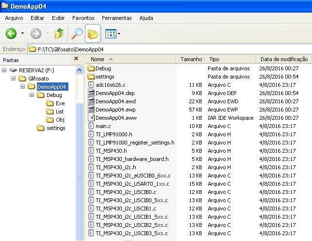
  • This is the file structure used in the program-example of the "demoapp04" (Texas Instruments) for configuration testing and output voltage measurement amplifier LMP91000.

    Sds,

  • This is the compilation of example "demoapp04" in IAR program.

    Sds,

  • It is interesting to analyze the reconfigurations needs in main.c, especially in lines 131 at 148:

    Sds,

  • In ADC16S626.C file, the line 13 is different from the configuration in "main.c":

    Then, a pin needs to be changed: SPI Bus - (GPIO) (P 2.0)


    Sds,

  • The communication via the I2C bus with a LMP91000 was defined by USCI B1 as choice in F5529. This choice in F5528 program demand a change in the lines 69 and 70, the "TI_MSP430_hardware_board.h" library, which defines the pins to be used in this communication.
    69 should be commented and 70 must be set.
    The other archives and libraries of I2C can be removed from the project.


    Sds,

  • To set the functions AD conversion of the pins was necessary to change 5 lines in the library "TI_MSP430_hardware_board.h".

    This was necessary due to the availability of pins in F5529 board.

    Sds,

  • Tests indicate the ultimate solution for interfacing between LMP91000EVM and MSP-EXP430F5529LP and data visualization possible through a PC:


    Sds,

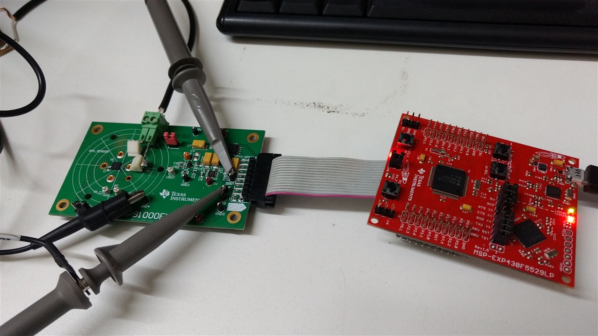
  • Was made a flat-cable with pins 90° bar to the connections between the MSP-EXP430F5529LP and LMP91000EVM.

    Sds,

  • Few changes were needed in the library "TI_MSP430_hardware_board.h" and pin connections between the boards under test.

    Sds,

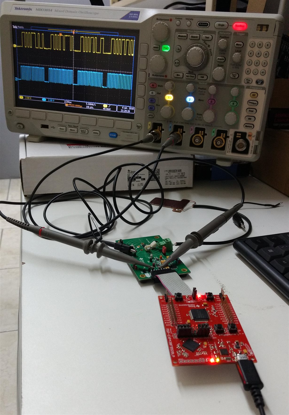
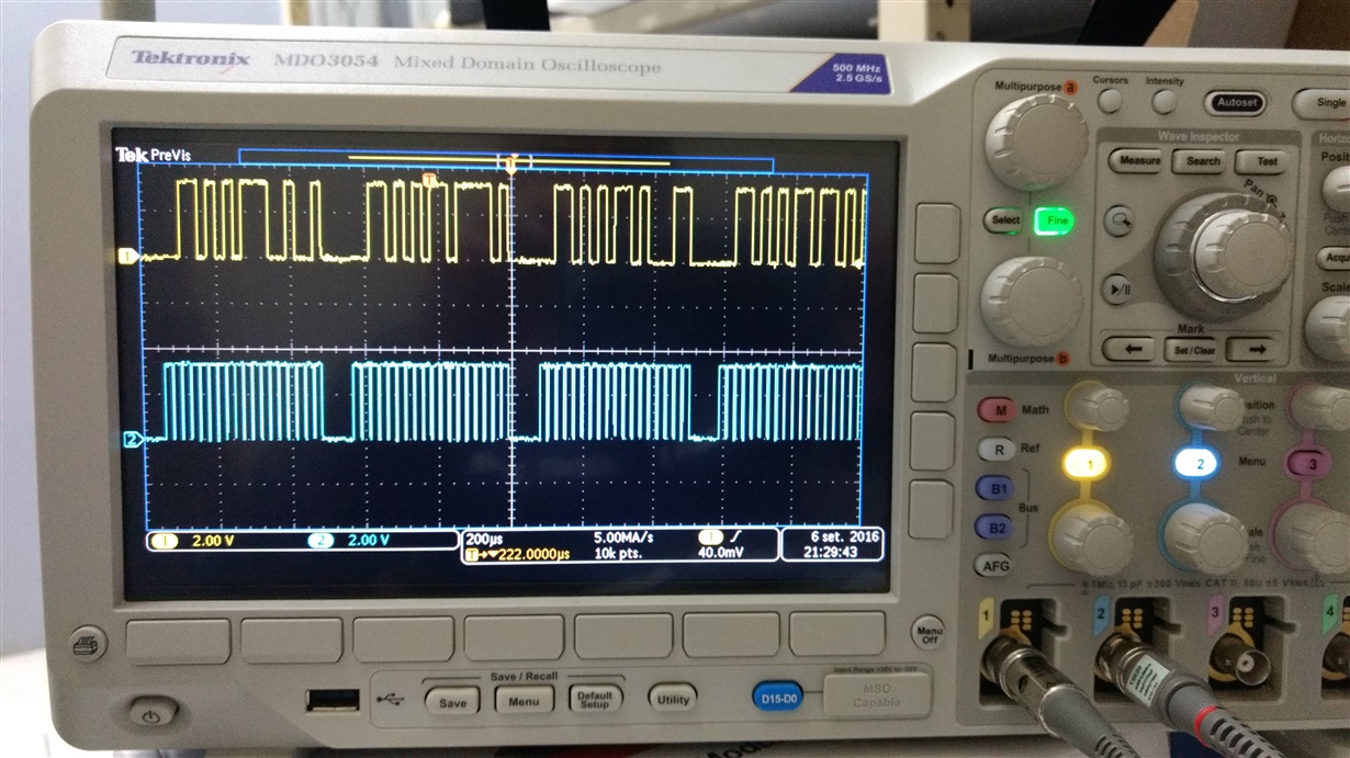
  • It was possible to see through a digital oscilloscope data traffic in AD converter LMP91000EVM transferred to the MSP-EXPF5529LP board.

    Sds,

  • Besides the measures of AD conversion data blocks, it was possible to visually measure the amplifier's output voltage LMP91000, properly polarized and delivering at its output an offset of 67% of "Vref", approximately 1.7 Vdc without sensor coupled in input.

    Sds,

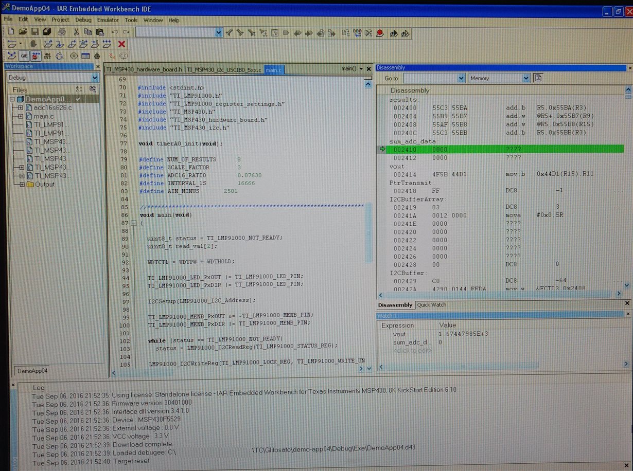
  • The approach of tension "vout" in IAR compiler was high for the measure on the oscilloscope, with the value of 1.67447985 Vcc.

    Sds,

  • In the library "TI_LMP91000_register_settings.h" contains the amplifier settings LMP91000.
    The datasheet LMP91000 (http://www.ti.com/lit/ds/symlink/lmp91000.pdf) specifies and clarifies each of the configuration options on the amplifier gain, polarization and operating modes on page 17 to 23 .
    Below the main settings listed in the example-4 of snac032 (http://www.ti.com/lit/sw/snac032/snac032.zip), among other possible:


    /************************************************************
    * TI LMP91000 REGISTER SET INITIALIZATION VALUES
    ************************************************************/

    #define TI_LMP91000_TIACN_REG_VALUE (0x03)          /* default */
    #define TI_LMP91000_TIACN_REG_VALUE (0x10)          /* TIA_GAIN = 14kohm, RLOAD = 10ohm */
    #define TI_LMP91000_TIACN_REG_VALUE (0x0C)         /* TIA_GAIN = 7kohm, RLOAD = 10ohm */

    #define TI_LMP91000_REFCN_REG_VALUE (0x20)       /* default */
    #define TI_LMP91000_REFCN_REG_VALUE (0xC0)      /* External Ref, INT_Z 67%, 0% bias */
    #define TI_LMP91000_REFCN_REG_VALUE (0xA0)       /* External Ref, INT_Z 50%, 0% bias */
    #define TI_LMP91000_REFCN_REG_VALUE (0x20)       /* Internal Ref, INT_Z 50%, 0% bias */

    #define TI_LMP91000_MODECN_REG_VALUE (0x00)   /* default */
    #define TI_LMP91000_MODECN_REG_VALUE (0x06)   /* Temperature Measurement Mode (TIA OFF) */
    #define TI_LMP91000_MODECN_REG_VALUE (0x03)   /* 3lead */
    #define TI_LMP91000_MODECN_REG_VALUE (0x81)   /* FET_Short enable, 2-lead ground referred galvanic cell */
    #define TI_LMP91000_MODECN_REG_VALUE (0x01)   /* FET_Short disable, 2-lead ground referred galvanic cell */

    Sds,

  • It was made impossible the use of MSP-FET430UIF due to technical limitations. However, the use of MSP-EXP430F5529LP was successful.

    Sds,
  • The interface "AFE Sensor for LMP91000" features a database with different detectors sensors gas and its multiple configurations, although only work with the data acquisition card "AFE Sensor Digital Controller Board" (http: //www.ti .com / tool / SPIO-4).


    Sds,

  • The AFE Sensor interface (www.ti.com/.../lmp9xxxxsensordev-sw) has a command that generates a .CSV file with the values ​​of registers and settings for a particular chosen sensor.

    Sds,

  • In the Excel program can be viewed parameters of the configuration for LMP91000 being listed as address (register) and value (setting).


    Sds,

  • There are 7 configuration parameters, but only 5 are essential, in this example:
    Address, Value:
    0x00 - 0x00 (Status Register - Ready)
    0x01 - 0x01 (Protection Register - Read only mode)
    0x10 - 0x0C (TIA Control Register - 7kohm, 10ohm)
    0x11 - 0xb0 (Reference Control Register - External, 50% Negative 0%)
    0x12 - 0x81 (Mode Control Register - Enabled 2-lead ground Referred galvanic cell).
  • If it were possible to use the interface "Sensor AFE" without the controller card "AFE Digital Sensor Controller Board" would be a great display option sensor behavior due to availability of settings and signal monitor. But would not such an expensive purchase so only USD $ 149.00 + shipping USD $ 6.99.

    Sds,

  • The virtual device is free and simple to use.


    Sds,

  •  Despite the limitations, there are some hardware and software information about the SPIO-4 that can help in a development project for data acquisition. www.ti.com/.../snau112.pdf

    Sds,

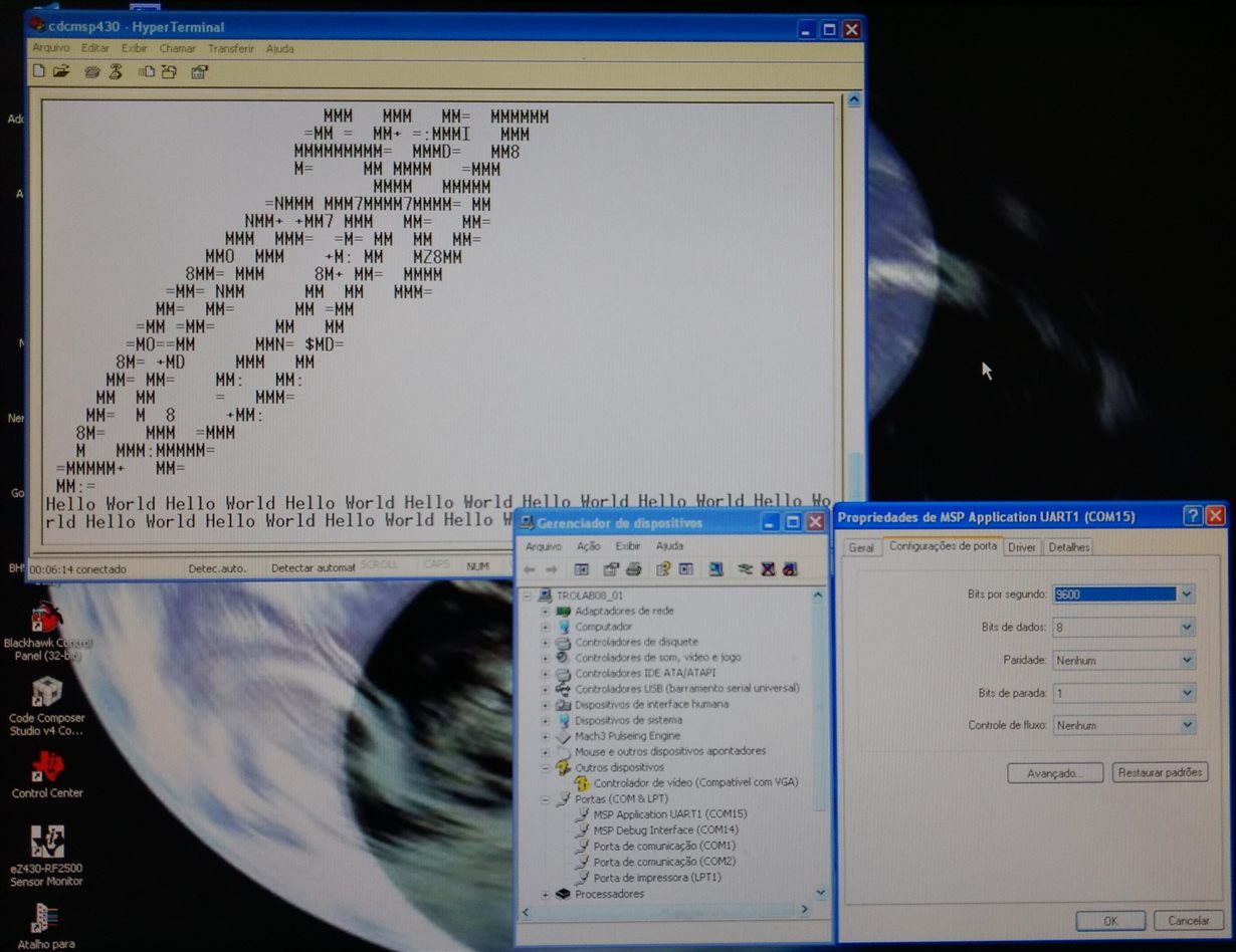
  • Finalizing the serial communication process, we have the opening of the program-example of the debug screen "Demoapp04" where you can observe the behavior of some variables and constants of the code.

  • When running the program in the IAR Compiler with "Breakpoint" applied on line 166 of the main can already be identified values of variables and constants in the "Watch 1" window.

  • When creating a serial connection using Windows XP Hyperterminal program through a serial port emulated the CDC process and settings for communication in C ++ language in the main is possible to follow the change in the value of "sum_adc_data" which presents average results of 8 AD conversions per second.

  • The values of "sum_adc_data" can be configured in Hyperterminal to present a reading by line of serial monitor on the PC.

  • The readings from the AD conversion represents the variation of the amplifier output voltage LMP91000 test and may be stored in a file type .HT to load an Excel spreadsheet, for example. Thus, it can be obtained easily behavioral graphics electrical signal proportional to the input sensor for gas detection.