I have a customer asking the following question:
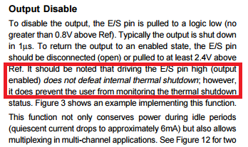
I am planning to use two OPA549s in bridge configuration. If one of the OPA549s goes into thermal shutdown, it is highly undesirable for the other one to remain operating. It would seem that if the E/S pins of both OPA549s are connected together and the E/S pin of the OPA549 in thermal shutdown can sink sufficient current to pull the E/S pin of the other OPA549 low, then both OPA549s will be disabled as desired. I also need to be able to disable the OPA549s in response to an external signal. To do this, I would connect an open collector NPN to the E/S pins (connected together as above) to pull them down. What is your assessment of using the OPA549 in this manner?
Would this configuration work? Can you send me a drawing of a configuration that would work?
I downloaded the OPA549 macromodel from the TI website, generated a symbol and ran some simulations in LTspice. My simulation testbench has the OPA549 configured for a gain of -1 with a 1V input and +/-15V supplies. I ran a temperature sweep and was expecting to see a -1V output up to 160C and 0V above that (I have a large valued resistor from the OPA549 output to ground). I did NOT see that for a result (not even close), so I ran a DC operating point simulation at 80C. The observed output voltage implied that the model had an 80mV input offset at that temperature. A DC operating point simulation at 27C yielded the expected result. Pulling down E/S to disable the OPA549 also appeared to work correctly at 27C. It was my intention to try to use the model to answer the questions I have posed to you about E/S pin behavior. After seeing the simulation results, I thought that perhaps the macromodel was intended for nominal temperature only.
Will the macromodel properly simulate the operation of the OPA549 over temperature?
Thanks for your help with this!
Richard Elmquist


