This thread has been locked.

If you have a related question, please click the "Ask a related question" button in the top right corner. The newly created question will be automatically linked to this question.

INA126UA/2K5 input protection circuit

Other Parts Discussed in Thread: INA126, INA827

Dear TI, 

I´m designing a DC voltage measurement up to 1000V DC with an INA126UA/2K5 instrumentation amplifier.The signal level on the input of the amplifier will be 2 V at 1000V DC input voltage, 1V at 500 VDC and so on. The output of the INA126 must have an voltage from 0-10V at 0-1000V input voltage. There are also some other measuring ranges. (0-10V at 0-350V input voltage). The gain is set with an BCD switch with sets the resistors Rg.


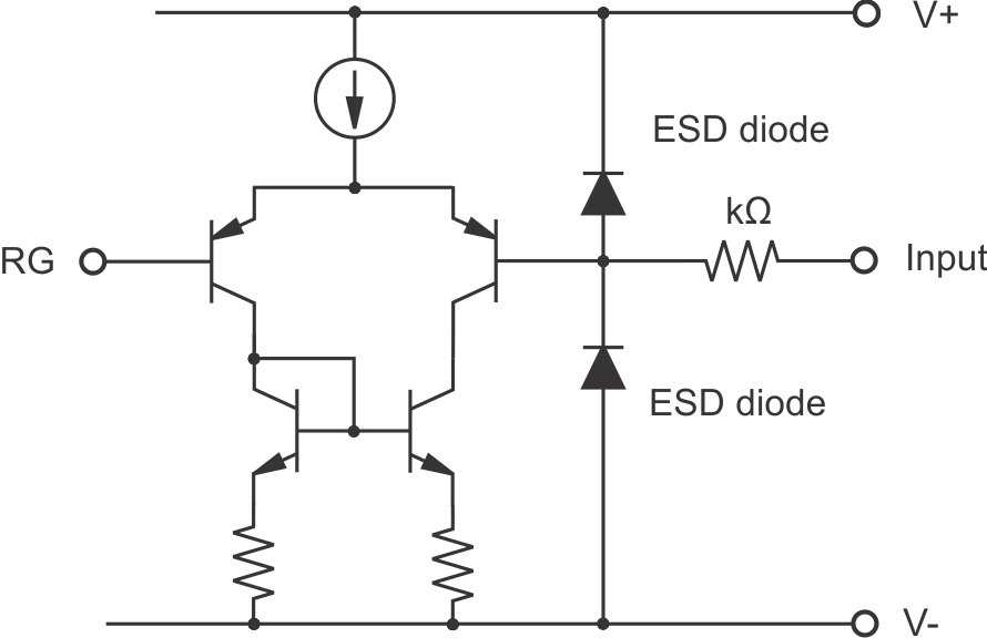
In the dataseet there is mentioned that for input protection of the amplifier there ar some internal diodes connected to the power supply rails.
Do i need some additional protection diodes between the Pin 3 and Pin 8 and between  Pin 1 and Pin 2 for differential voltage protection of the two amplifiers?
Do you have a drawing from the input circuit of the INA126 where i can see the existing protection diodes? (Like the figure 56 of INA827 datasheet)

Thank you for your help

  • Hi Manuel,

    The INA126 differential input stages use a PNP pair that can withstand the absolute maximum rated differential voltage of (V–) – 0.7 (V+) + 0.7. The design does not require input-to-input diode clamps. The internal input diodes are ESD protection diodes connected from each input to each power supply rail. They are intended for out of circuit ESD protection when the device is being handled during board assembly. They are not activated in normal circuit operation.

    You should not have to add external clamping diodes unless you anticipate the applied input voltage can exceed the absolute maximum input specifications. Adding external protection devices can introduce input leakage current and can sometimes increase distortion. Only add them if added protection is required.

    I have drawn a simplified schematic for the INA126 op amp input stages and it is shown below. You can see how the ESD diodes are connected internally.

    Regards, Thomas

    PA- Linear Applications Engineering