This thread has been locked.

If you have a related question, please click the "Ask a related question" button in the top right corner. The newly created question will be automatically linked to this question.

DOUBTS AFE031

Other Parts Discussed in Thread: AFE031

Hello everybody,

My design is a 24V power line communication. I have set the AFE031 as shown in the TIDU160 PDF from TI... i have connected the AFE031 to 24V (24V IN) and the other pins to 3,3V and 15V as shown in that datasheet... I send from a microcontroller to the DIN pin a sequence of 10bits with a clock signal going to the SCLK pin, doing this:

  • Set CS low.
  • Set the DAC pin (pin 7) high.
  • Write a 10-bit word to DIN.
  • CS high updates the DAC.
  • set the DAC LOW

the clock signal is 20ms (10ms HIGH and 10 ms LOW)  50Hz..

when i try to read the 24Vin, it has no change and no modulation, it keeps being stable at 24V..

what is happening why i cant see the modulation?

thanks and best regards,

Andres

  • update:

    it seems I am receiving something from the pin 14..but it is the opposite what i should receive, for example:

    I send 1111-1111-11 (10 bits) to the dac register and i receive a 0V in the pin 14.
    i send 0000-0000-00 (10 bis) to the dac register and i receive 1.4V in the pin 14.

    I have set the register:
    enable1= set dac,rx,tx and PA bit
    enable2= set ref2,ref1 bit

    anyway in my power line i cant see any modulation, it keeps staying at 24V

    in the PA_OUT (pin 43 and 42) i get 6V always.

  • If you have not debugged this issue yet please post your schematic and listing of you code so I can look into it.

  • Good afternoon,

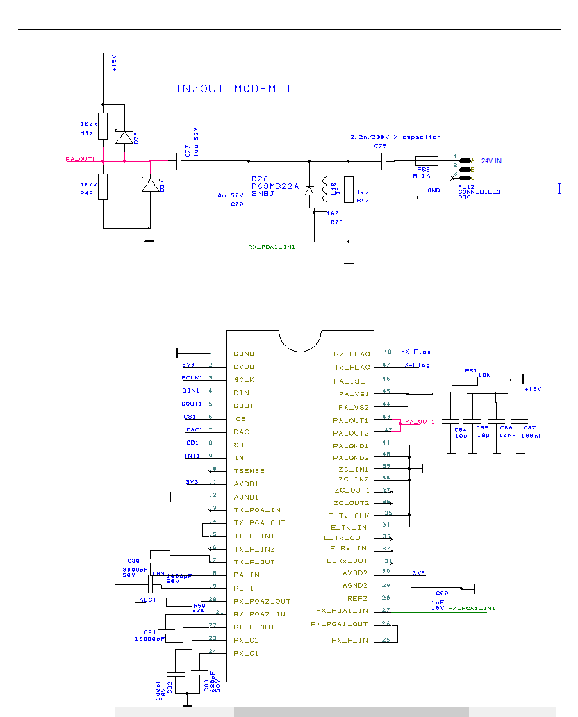
    Here is my schematic, following what the tidu160 PDF from TI says:

    My code is a bit complicated but I did an special code just to see if the AFE031 responds and gives me an output, here is that easy code:

    #ifndef F_CPU // if F_CPU was not defined in Project -> Properties
    #define F_CPU 1000000UL // define it now as 6 MHz unsigned long
    #endif

    #include <avr/io.h> // this is always included in AVR programs
    #include <util/delay.h>
    #include <avr/interrupt.h>

    int main(void)
    {
    DDRB &= ~(1 << PB2); // clear DDRB bit 2, sets PB2 (pin 3) for input DOUT FROM MODEM
    DDRA |= (1 << PA1); // set DDRA bit 1, sets PA1 (pin 19) for output SCLK TO THE MODEM
    DDRA |= (1 << PA2); // set DDRA bit 2, sets PA2 (pin 18) for output DIN TO THE MODEM
    DDRA |= (1 << PA4); // set DDRA bit 4, sets PA4 (pin 14) for output CS TO THE MODEM
    DDRA |= (1 << PA5); // set DDRA bit 5, sets PA5 (pin 13) for output DAC TO THE MODEM
    DDRA |= (1 << PA6); // set DDRA bit 6, sets PA6 (pin 12) for output SD TO THE MODEM
    DDRA |= (1 << PA7); // set DDRA bit 7, sets PA7 (pin 11) for output INT TO THE MODEM

    int i, iter;
    int address1=500;

    PORTA |=(1 << PA4);                       //SET CS
    _delay_ms(500);
    PORTA &=~(1 << PA5);            //CLEAR DAC
    _delay_ms(500);
    PORTA &=~(1 << PA4);           //CLEAR CS
    _delay_ms(500);
    PORTA |=(1 << PA5);               //SET DAC
    _delay_ms(500);

    while (1)
    {
    for (i=512, iter=512; i>=1; i>>=1, iter--) //check every bit of the command
    {
    if (address1 & i)
    PORTA |=(1 << PA2); //DATA SIGNAL HIGH
    else
    PORTA &=~(1 << PA2); //DATA SIGNAL LOW

    _delay_ms(500);
    PORTA |=(1 << PA1); //CLOCK SIGNAL HIGH
    _delay_ms(500);
    PORTA &=~(1 << PA1); //CLOCK SIGNAL LOW
    }
    PORTA &=~(1 << PA2); //DATA SIGNAL LOW
    _delay_ms(500);
    PORTA |=(1 << PA4);                                //SET CS
    _delay_ms(500);
    PORTA &=~(1 << PA5);                       //CLEAR DAC
    _delay_ms(10000);
    PORTA &=~(1 << PA4);                        //CLEAR CS
    _delay_ms(500);
    PORTA |=(1 << PA5);                              //SET DAC
    _delay_ms(500);
    }

    }