This thread has been locked.

If you have a related question, please click the "Ask a related question" button in the top right corner. The newly created question will be automatically linked to this question.

OPA192 V-I conversion circuit phase margin

Other Parts Discussed in Thread: OPA192

Dear support team

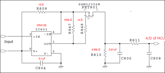
My customer is going to design the V-I conversion circuit using OPA192.

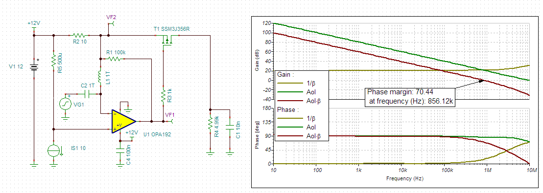
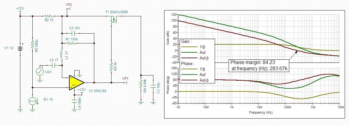
I want to confirm whether this circuit do not oscillate it, but simulation does not go well.

Could you advise it? (Please see attached file)

◆Condition

・They use OPA192 for current detection circuit of the high side

・Supply voltage:12V

・Common mode voltage:12V

・Gain:499

・Shunt resister:0.5mΩ

Regards

Tomohiro Nagasawa

  • Hello Nagasawa-san,

    We are also experiencing issues with the convergence of this circuit while using the SSM3J356R FET shown in your schematic.  It is not uncommon to experience issues while running small-signal transient analysis on complex circuits with op amps and active components in the feedback path.  We were able to run ac open-loop simulations to verify the circuit phase margin, but transient simulations were not possible due to convergence issues in the simulation engine.  Without any additional compensation the circuit phase margin looks to be >70degrees.  However, there is a zero in 1/Beta slightly above the unity-gain frequency that over process variations and component modeling tolerances may cause issues.  Therefore we recommend adding the high-frequency feedback loop around the PMOS as shown in the second circuit and results.

    Modified circuit with 15nF in parallel with the 100k resistor:

    Modified_Open-Loop.TSC

    Original_Open-Loop.TSC

  • Hello Collin-san

    Thank you for quick response and simulation.

    I try to recommend additional capacitor.

    Thanks

    Best Regards

    Tomohiro Nagasawa