This thread has been locked.

If you have a related question, please click the "Ask a related question" button in the top right corner. The newly created question will be automatically linked to this question.

LF198H Sample and Hold Circuit

Other Parts Discussed in Thread: LM339, LMV339-N, LMV339, OPA192, LM324, LM234

Question : I am trying to use the LF198H as a peak detector. The supply voltage to the "metal can" is +15 volts and - 15 volts. The input signal is -10 volts to +10 volts. I used to use a Analog Devices PKD01 for this purpose. It has been discontinued by Analog Devices.      For my circuit, the the typical input signal may go from - 3.0 volts up to +1.2 volts in 2 seconds, and then drop back to th original -3.0 volts. With the PKD01 circuit, I would go low with the logic input, and the output would match the maximum of the input and stay at that level even when the input would drift back to -3.0 volts. the output would stay at +1.2 volts ( the peak ), until the ligic input was set to high again. At that point, the output would match the input, until the logic input went low again. At that point, the whole process starts over again.  Is it possible to replicate the function of the PKD01 with the LF198H ? Please help.

  • Hello Steve,

    The LF198/LF398 will not function as a peak detector.

    The amp output driving the cap can both sink and source, so the voltage on the storage cap will follow the input, on both rising and falling voltages. It was designed to "freeze" the last voltage before the trigger.

    You would need a diode between the output of the buffer amp and the storage cap to keep the amp from discharging the cap when the input voltage decreases. That is the function of D1 in the PKD01 block diagram.

    Just google "Peak detector" and you will see MANY, MANY examples of peak detector circuits (of various speeds ad complexity).

    Although a cute one that uses a comparator is shown on the LMV339-N datasheet apps section. Though shown as a single supply, it would also work on a split supply. The LMV339 is a 5V device, so you would need a higher voltage device, like the LM339. The comparator needs to be fairly fast, as it is "PWM'ing" it's output to create the output voltage (treat it as a high-speed circuit - with good supply bypassing and short traces).

    Regards,
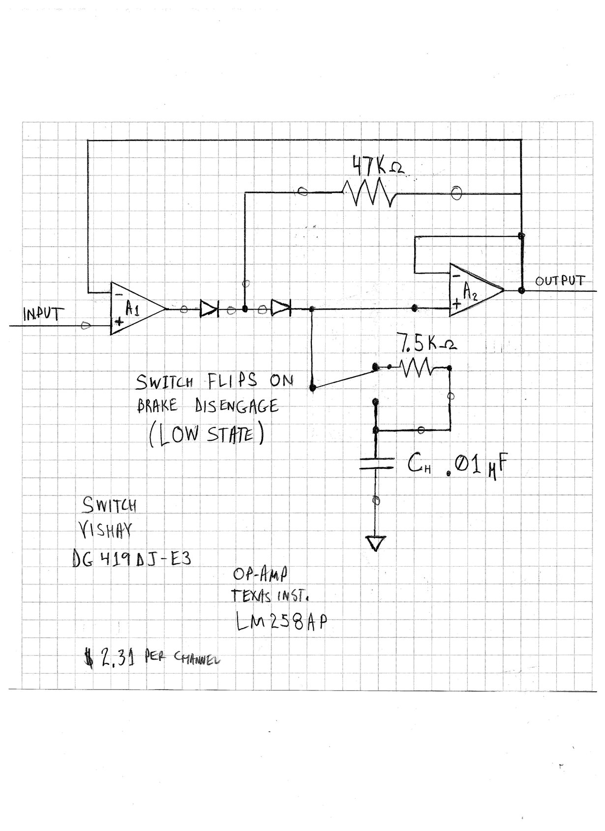
  • Hello Paul, Thank you for the assistance with the peak detector circuit. I ended up using a Texas Instrument LM258AP OpAmp. I scanned in the schematic for you to get a good chuckle. I am using an analog switch in the circuit because I want the output voltage to follow the input voltage when the circuit is not in peak collect mode. I also wanted the capacitor voltage in relatively the same neighborhood when the peak voltage acquisition window is initiated. Thanks again for your help.

  • Hi Steve,

    Hmmm...I'm note sure it will do what you want.

    Flipping the switch really does nothing...other than limiting the current into the cap. The cap is not big enough to hold the voltage against the amplifier output, thus the "peak holding" will still continue, even with the switch flipped to 'hold" mode.

    Instead, I would recommend replacing the right-hand diode with the CMOS switch, so that it completely disconnects the cap from the driving amp.

    In short - duplicate the ADI circuit (though the ADI circuit uses a current to charge the cap...so it is a little more sophisticated).

    You are also missing a diode and feedback resistor clamp around the first amplifier which keeps the output of the amp from railing on the negative side. See the following example below (ignore the 30pF cap -  that is specific to the LM101 - and any op-amp can be used).


    You also want to increase the 47K resistor to 1M, as this resistor bleeds a little current into the diode to cancel the leakage. R2 is a bias cancelling resistor - not needed if you use a JFET or CMOS input device (see below).

    So you would put the switch between D2 and C2.

    The problem you will run into is that during hold, the first amplifier goes open loop when you "hold", since the outer loop feedback is broken. That means the first amp output will rail. When you go back to tracking, there will be an initial "glitch" and recovery time as the loop re-stabilizes. D3 above will clamp the first amp output to ~300-700mV of Vin (reduce R2 to 100k or so to prevent too much current through D3). So the output would only move <800mV, instead of volts.

    Probably the simplest way that eliminates overdrive, glitches and settling issues, is to use a third buffer amp and disconnect the cap completely from the circuit, then just buffer the resulting voltage on the cap. Then the peak loops continue in-tact and are immediately ready for the next cycle.

    Either way, you need a way to reset (short) the cap - otherwise it will (theoretically) stay at the highest peak received over the entire time (minus leakage droop). There should also be at least 200 ohms in series with the cap to prevent the amplifier from oscillating - preferably before the switch (switch input capacitance can also cause oscillations).

    This circuit begs to be simulated...I recommend you try a few simulations to make sure the circuit is working as you think...in both track and hold modes.

    Minor notes:

    In your circuit, there is also a potential of the first amp oscillating when the switch is in the hold mode where the capacitor is placed directly on the output of the amp. I have seen these oscillations occur even through diodes (creating very weird looking oscillations). The resistor in series with the cap (>200 ohms) will prevent this.

     I would use a 30V JFET or CMOS input op-amp, like the LF41x or TL08x series (cheap), or newer ones like the OPA192 (high performance, low offset).

    The LM234 bias currents are in the nanoamps and will cause 'droop" during hold. Also, the LM234 (LM324) output stage has a "feature" that makes it difficult to drive light loads (<50uA). Normally a pull-down resistor is required if using this device with small loads. I would avoid using the LM234 in this application.

    Regards,

  • Hello again Paul, The "diode and feedback resistor" schematic did not come through. It showed up as a black "x". I think I have seen what you are talking about on a couple of the images that I saw when searching the Internet for peak hold circuits. Getting back to my original schematic... The 7.5K Ohm resistor is to keep the charge of the hold capacitor in the relative range of the input voltage just prior to a peak hold cycle. The issue is, the machine may be at rest for a couple hours before being used for 6 hours. The input voltage is permitted to drift around until it's time to perform a peak hold cycle. The peak hold window is open for about 2 seconds. The whole issue is the input voltage changes at 6000 Hz. The data acquisition can only process and look for a peak at about 100 Hz. Your comments are more than welcome. Thanks again for your time. SFR