This thread has been locked.

If you have a related question, please click the "Ask a related question" button in the top right corner. The newly created question will be automatically linked to this question.

INA333 for ADC driving

Other Parts Discussed in Thread: INA333, REF2025

Hello!

I'm going to drive Sigma-delta ADC with INA333, the input source will be magnetic loop with 20 Ohms impedance, source signal ~0-30Hz, ADC reference REF2025 (1.25v + 2.5v),
main power 3.3v (battery)

Should i connect power pin of INA333 to 3.3v or 2.5v?

What resistors (R2,R3) are better?

Should i connect the middle-point of magnetic loop to virtual ground (1.25v)?

  • The function of connecting the inputs via resistances to ground is to provide a path for the input bias current to flow to ground. In this case, your resistance values for R2 and R3 seem to be fine, since they will cause an offset voltage of around 20uV, which is lower than the V_os of the INA333 of 25uV.

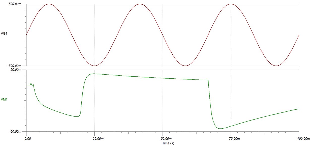
    I simulated your design in TINA and I see output clipping when the magnetic loop is connected to virtual ground:

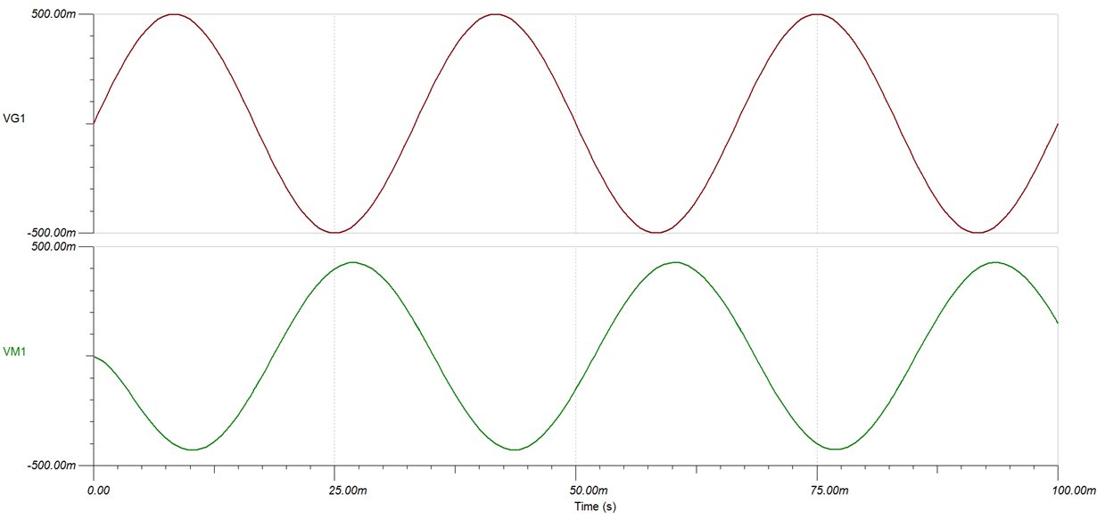
    When the magnetic loop midpoint is connected to supply ground, the distortion disappears:

    So I would recommend connecting the magnetic loop midpoint to supply ground.

    Best Regards,

    Mihir Gupta,

    Field Applications Engineer

    Texas Instruments

  • Hello again!

    I simulated design with magnetic loop connected to the reference 1.25v and i seems to be ok,

    (the input signal is 10 mV)

    Connecting middle point to ground provides corrupted signal:

    Original TINA project:

    ina333.TSC

  • Direct connecting provides the same result, Which design is preferred?

    OR:

    Direct:

    ina333-Direct.TSC

  • Hi Alexander,

    There seem to be two issues at play here that were affecting the output of the circuit.

    1. In the initial schematic that you sent me, the V+ and V- of the INA333 were connected directly to the DC power supply without referencing them to a ground. This would not cause issues in the real-world circuit (since the V- would be connected to the power supply ground anyway). However, because of the way that the Spice simulator works internally, it can cause some discrepancies in the circuit model and simulation. Hence it is usually recommended to connect the ground of your spice circuit to the power supply ground, since that is what your real world circuit will be referenced to.

    2.  I went back to the circuit that I posted earlier and changed it to match your new INA gain and input signal. It turns out that the output did indeed have distortion but the large output capacitance in my design filtered it out. My apologies for this oversight.

    These distortions were due to input common mode voltage limitations of the INA333. The graph for the Vcm vs. V_out of the INA333 is posted below:

    When we connect the midpoint of the magnetic loop to supply ground, we have a common mode voltage of 0V, which gives an output voltage swing of 1.05V to 1.44V.

    But when you connect the midpoint of the supply to the 1.25V Vref, you move the common mode voltage to 1.25V, which gives you a much larger possible output voltage range of 0.05V to 2.45V.

    Hence I would recommend that you use the schematic that you posted below:

    You can find the tool that I used to make the INA V_cm vs V_out graphs here, in case you would like to play around with other configurations:

    I hope this helps, please let me know if you have any more questions!

    Best Regards,

    Mihir

  • Thank you for the detailed answer