


Dear Sirs
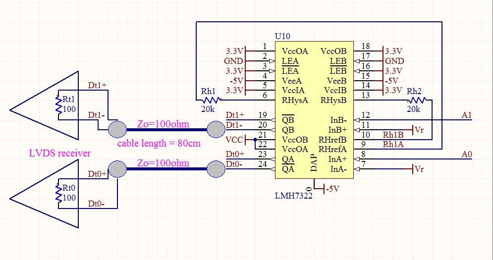
LMH7322 output to LVDS receiver
Signal input from A0 & A1, compare to Vr.
Reference circuit from LMH7322 data sheet Fig.24
But change the Vcci from 5V to 3.3V, Vcco from 2.5V to 3.3V.
Is the schematic ok?
BRS
Nat
Dear Sirs
LMH7322 output to LVDS receiver
Signal input from A0 & A1, compare to Vr.
Reference circuit from LMH7322 data sheet Fig.24
But change the Vcci from 5V to 3.3V, Vcco from 2.5V to 3.3V.
Is the schematic ok?
BRS
Nat
