This thread has been locked.

If you have a related question, please click the "Ask a related question" button in the top right corner. The newly created question will be automatically linked to this question.

INA219 measuring Solar cell short circuit current

Other Parts Discussed in Thread: INA219

Hello all,

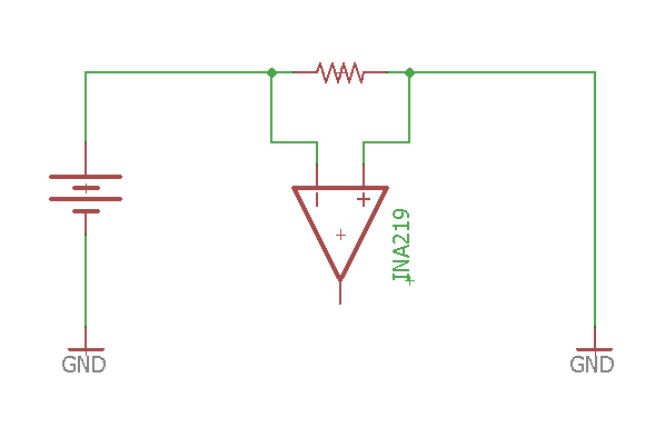
I recently acquired some small solar cells which I'm trying to characterize. They're rated for 6V at 100mA. While I can measure their open-circuit voltage easily, I also need to determine their short-circuit current values. In my opinion, this would involve connecting the solar cell + terminal to the Vin+ terminal of the INA219, and then connecting the Vin- terminal and solar cell - terminal to ground, essentially providing a "short-circuit" of sorts. However, there is a warning in the datasheet stating that situations resulting in large voltages being dropped across the shunt resistor (I'm using a 0.1 ohm shunt) should be avoided. Can anyone please tell me how to go about measuring this short-circuit current with the INA219, or if this is even possible with it?

Thanks!

  • Hi Madara,

    You can use the INA219 but the direct connection you are suggesting doesn't seems right. I would add a switch for your short circuit tests and connect the INA219 in a high side configuration. My idea is something like the circuit below. It is just an idea, no too much detail in this circuit. Hope this helps!

  • Hello Mayrim,

    Thanks, but the diagram above is really quite similar to my current setup. My concerns are specifically centred around the point where the switch is closed - in that situation, the load has been shorted out entirely, leading to a circuit that looks something like this:

    Which (in my understanding) means that the full voltage coming from the solar cell is dropped wholly across the shunt resistor. If I'm correct, that would mean around 1-5V would appear across the shunt resistor - which should not have more than 320mV dropped across it. What then happens in such a situation?

  • Hi Madara,

    The INA219 can handle up to 26V in the input pins as stated in the MAX Ratings table, with no damage to the device. But the INA219 linear range is up to 320mV, the behavior above that voltage can't be guaranteed. It won't damage the device but we don't know how much time the device will take to recover.
  • Hello Mayrim,

    Okay, thanks. Could you kindly suggest another TI part I could use to perform this measurement, or some other way of wiring the INA219?

    Thanks again