This thread has been locked.

If you have a related question, please click the "Ask a related question" button in the top right corner. The newly created question will be automatically linked to this question.

[ OPA4192 ] Output Instability from Noise Immunity Test

Other Parts Discussed in Thread: OPA4192, OPA192

[ OPA4192 ] Output Instability from Noise Immunity Test

Hi,

My customer is interested in OPA4192 for their industrial board and now trying to perform the noise immunity test.
During this noise test, the output from OPA4192 show a bit different behaviors comparing with another opamp.
Can you help to identify what is the issue on their board and how they would need to change?

Their schematics is as below.


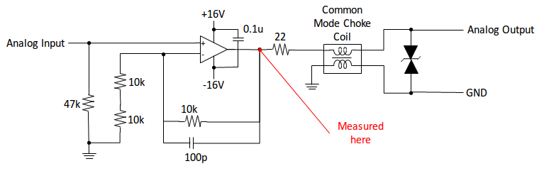
As you can see the waveform below, the output from OPA4192 is ocassionally inverted, while the output from competitor is not.


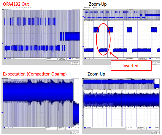
I have checked some points to customer.
* Output load should NOT be higher than 1nF.
* It's not easy to identify which pin of OPA4192 is affected from this noise.

I did think that the phase reversal protection is included into this device, and good EMIRR help to prevent this kind of issue...

Any ideas, comments and idea of alternative amps are highly appreciated!!
Thanks,
Ken

  • Hello Ken,

    The OPA192 has performed well against similar IEC61000-4-4 (EFT) testing when the signals are coupled into the outputs.  Could you answer the questions below so we can understand what type of disturbance the OPA192 is being subjected to?

    -Where and how is the noise test signal being injected into the system at? (inputs, outputs, through a magnetic clamp, etc.)

    -What test level is the circuit being tested at?  (1kV, 2kV, 1V/m, etc.)

    -What is the part number for the common-mode choke?

    -What is the part number for the TVS diode?

    -What is the part number for the competition device that performs well against the test?

    -Could you please attach pictures in a .ZIP file so we can zoom in and observe the results closer?

  • Hi Collin,

    Thank you for your support on this issue.
    Here I compiled some information based on your question


    ---
    -Where and how is the noise test signal being injected into the system at? (inputs, outputs, through a magnetic clamp, etc.)

    -What test level is the circuit being tested at?  (1kV, 2kV, 1V/m, etc.)

    See the drawing below. This is what I got from my customer with regards to their noise test.
    Their board will be used in conjunction with TIG welding machine, so it's assumed that the welding machine is placed close to OPA4192 board.


    -What is the part number for the common-mode choke?

    -What is the part number for the TVS diode?

    Common-Mode Choke: DLW21SN261SQ2 from Murata

    www.murata.com/.../productdetail

    TVS diode: RSB33VFH from Rohm

    www.rohm.com/.../RSB33VFH

    -What is the part number for the competition device that performs well against the test?

    uPC824G2 from Renesas

    www.renesas.com/.../UPC824G2.html

    -Could you please attach pictures in a .ZIP file so we can zoom in and observe the results closer?

    I'm asking the customer to share the files. I will share with you, once I have it.

    Thank you for your support in advance.
    Regards,
    Ken

  • Hi Ken,
    Thanks for the additional information. It looks like this is a conducted immunity test used to simulate the type of conducted energy that may be present in welding systems. The conducted energy is pretty large near 10MHz which is where the OPA192 will begin to run out of bandwidth and will decrease in it's ability to reject the noise signals. We still have a few more questions to try to work this out:

    Do you know if the noise test signal is injected through a coupling clamp sometimes called a "coupling donut"?

    If so, could you confirm which signals are being placed through the coupling clamp (i.e. Vout, GND, Vout &GND)?

    If the noise is being coupled through the analog inputs then it will pass through to the output because the op amp wouldn't differentiate the noise signal from the desired input signal.