This thread has been locked.

If you have a related question, please click the "Ask a related question" button in the top right corner. The newly created question will be automatically linked to this question.

INA826 AC measurement and Tina simulation

Other Parts Discussed in Thread: INA826

Hello,

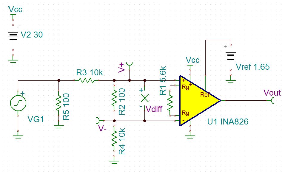
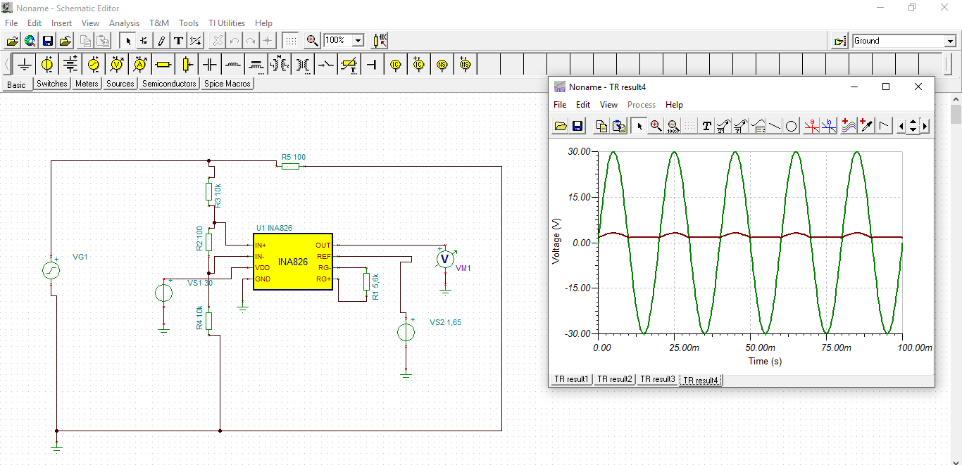
I would like to measure AC voltage using INA826. I designed a circuit and run simulation in Tina.
AC amlpitude: 30V, VDD=30V, Uref=1,65V. Is the circuit design correct? I expected the input to be just amplified and increased by Uref.

Thank you, Ondra.

  • Hello Ondra,

    Your expectations are correct—the differential signal between the positive and negative inputs on the INA826 should experience a gain based on RG (5.6k results in approximately 9.821V/V based on the equation in the datasheet) which is then added to the reference voltage. Vout = Vdiff * G + Vref, is the equation representation of this phenomenon.

    However, the design you provided is violating the common mode voltage limitations of the instrumentation amplifier which causes it to act nonlinearly.

    Since the INA826 is in single supply, the voltages on negative and positive terminal cannot swing below ground. Taking your circuit and putting meters on the positive and negative inputs of the INA826, you can see the waveforms swing below ground.

    This results in the flat portion on the negative swing of Vout. Part of this problem can be solved by putting the amplifier in dual supply (+/-15V) since this will allow the voltage to swing below ground at the inputs.

    However the 100k resistors—which I assume are meant to step down the input voltage—do not limit the input within the common mode voltage limitations defined by the voltage supplies. After changing the supply voltages to +/-15V, try making the input amplitude 10V, you should see the output create a sine wave of appropriate gain centered on Vref. If the input amplitude cannot be attenuated by changing the parameter, a difference amplifier could do a better job limiting your +/-30V input voltage swing.

    Since your application is to sense a current across a resistor, a current shunt monitor may be an alternative device to solve your problem. You can find a list of the products here.

    I also recommend you take a look at the video series provided by TI Precision Labs regarding input and output limitations if you are unfamiliar with the concepts discussed in this post.


    Best,

    -Cole